Integrated infusion management system
a management system and infusion technology, applied in the field of support stands, can solve the problems of stability and/or storage deficiencies of conventional iv pole systems, and achieve the effects of convenient and easy use, increased stability and resistance to tipping
- Summary
- Abstract
- Description
- Claims
- Application Information
AI Technical Summary
Benefits of technology
Problems solved by technology
Method used
Image
Examples
example 1
IMS Geometry
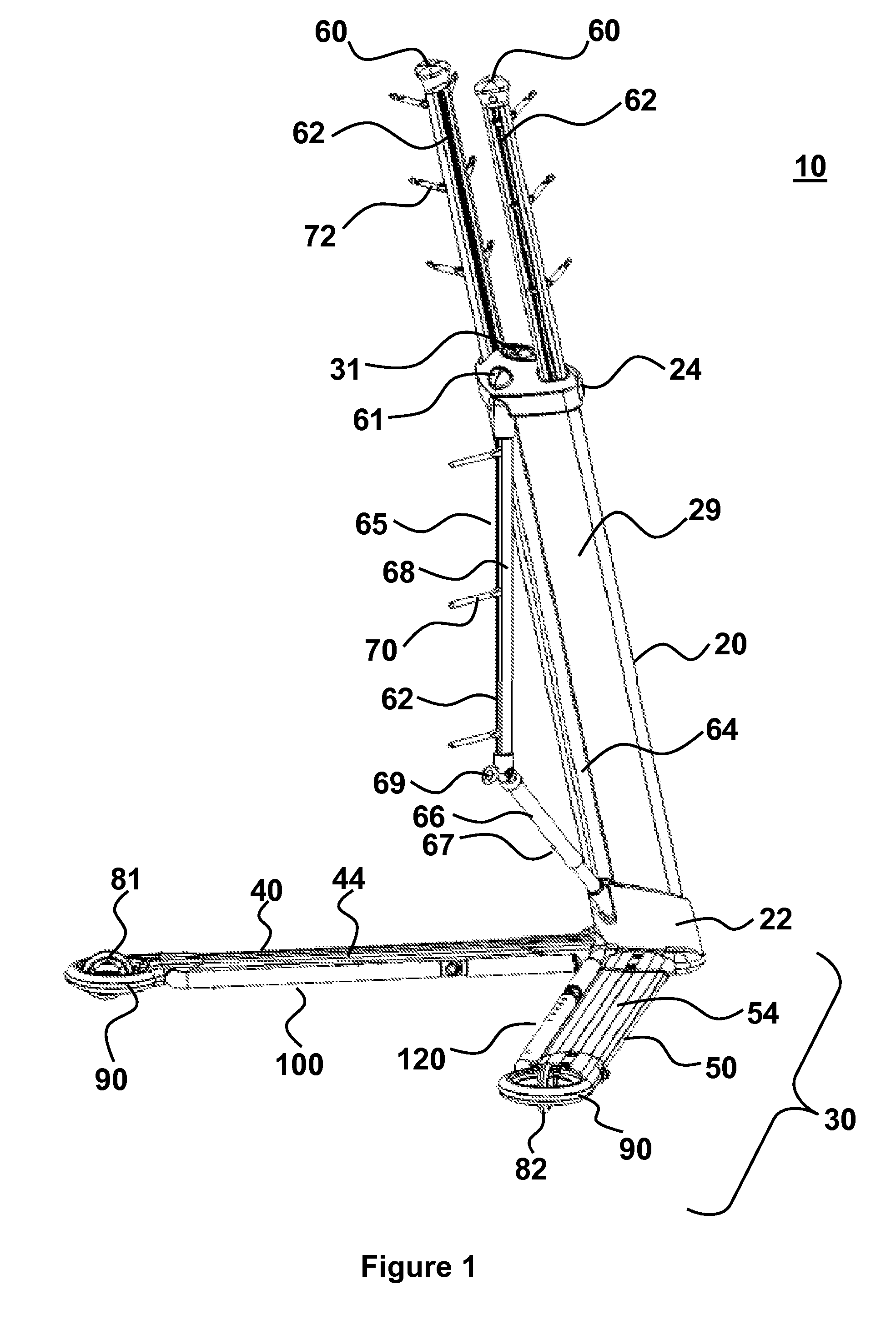
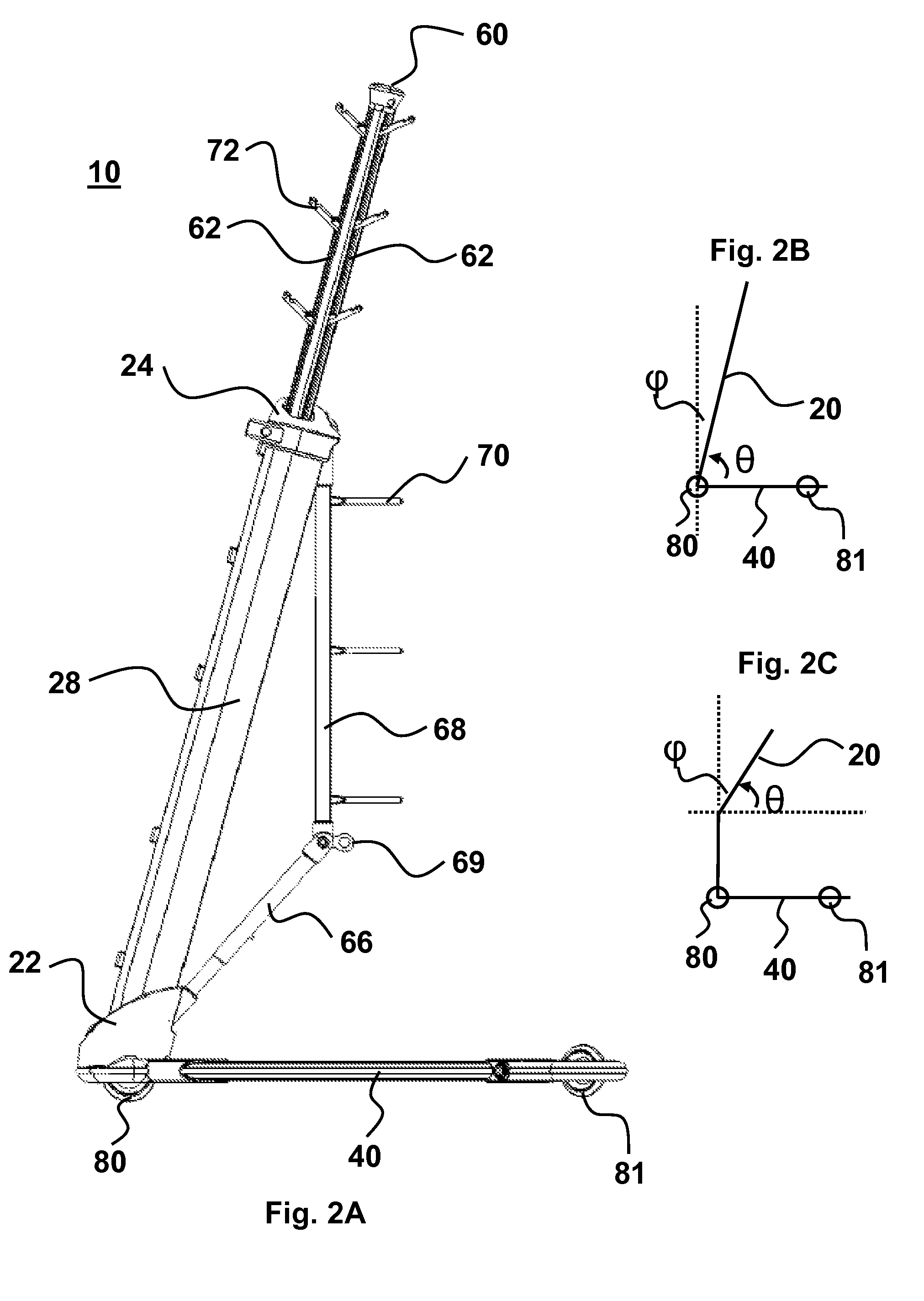
[0108]The infusion management system (IMS) in its most basic configuration comprises a base 30 having a first 40 and second 50 base arm connected to a trunk 20 (FIG. 1). FIGS. 1-6 show an IMS in the base deployed configuration 10. Base arms 40 and 50 are connected to trunk 20 bottom end 22. The trunk 20 has at least an axial portion corresponding to a non-zero angle relative to vertical and an acute angle relative to base arms 40 and 50. This geometry is summarized in FIG. 2B, with the acute angle formed between trunk 20 and base arm 40 (or 50) labeled as θ and the non-zero angle relative to vertical labeled as φ. In the exemplified embodiment of FIGS. 1-6 (e.g., three wheels deployed), the wheels 81 and 82 attached to base arms 40 and 50, and wheel 80 attached to trunk bottom 22 form a base footprint 32 that is triangular (e.g., see top and bottom views in FIGS. 3 and 4B). Base footprint 32 refers to the triangle defined by the contact point between each of the three wh...
example 2
IMS Walker / Mobility Assistance
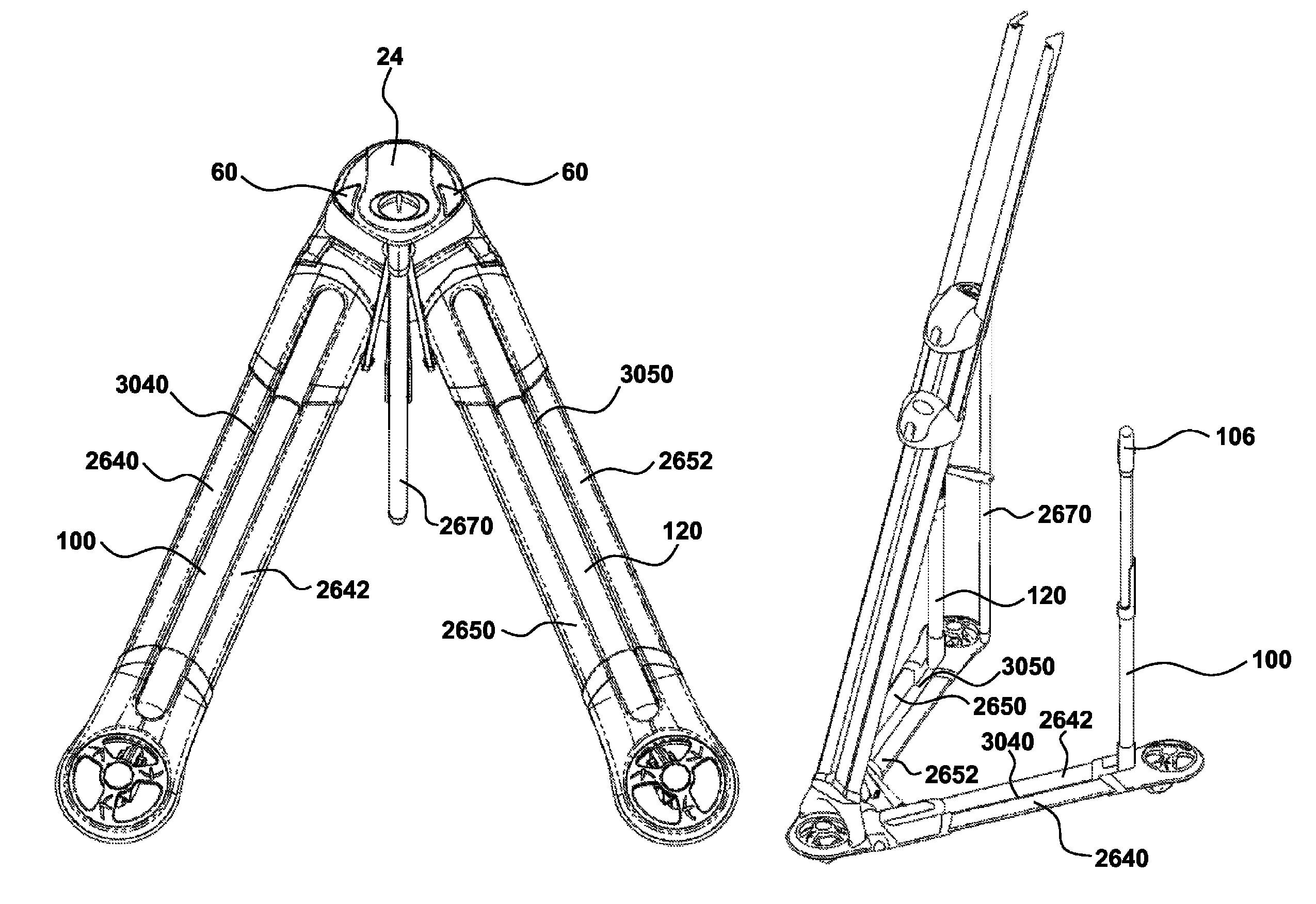
[0117]A useful embodiment of the invention is a system that has mobility arms 100 and 120 deployed such that the system is in a base and walker deployed configuration 12 (FIGS. 7-12). FIGS. 1-6 illustrate base-only deployed configuration 10, and FIGS. 7-12 illustrate a system in a base and walker deployed configuration 12. Mobility arms 100 and 120 are connected to base arm 40 and 50, respectively (FIG. 7). The mobility arm 100 and 120 are each pivotally connected to base arm 40 and 50, respectively, so that the mobility arms are deployable. In the exemplified embodiment this pivot connection 102 is located at the inner surface of each base arm (FIG. 8). The connection can also be at other positions, such as the top surfaces 44 and 54 of the base arms 40 and 50 or outer facing surfaces of base arms. Mobility arms 100 and 120 are capable of locking into a deployed position (FIGS. 7-12) or a stored configuration (FIGS. 1-6) by a handle lock assembly 101 t...
example 3
IMS Storage
[0121]FIGS. 13-18 illustrate the system in its stored configuration 14. In particular, each of the individually deployable components (wheels 81 and 82, base arms 40 and 50, handle grip 106, handle (100, 120, 104, 105), holding arm 60, collapsible support 65, holders 70 and 72) are stored to provide maximum compactness. Wheel 80, is shown deployed and can be used to assist in moving system 14 by rolling it over a surface to or from a storage location or to an area where it is to be deployed.
[0122]The system is able to be compactly stored, while retaining the ability to be quickly and easily deployed by a single person. For example, depressing base lock button 31 allows base arms 40 and 50 to unlock from their stored position (parallel to trunk 20) and into their deployed base configuration. Holding arm lock 61 is depressed to deploy holding arms 60 in a position ready to receive one or more medical components. Folding arm 65 is located within a trunk storage groove 64 in ...
PUM
 Abstract
Description
Claims
Application Information
 - R&D
- Intellectual Property
- Life Sciences
- Materials
- Tech Scout
- Unparalleled Data Quality
- Higher Quality Content
- 60% Fewer Hallucinations
Browse by: Latest US Patents, China's latest patents, Technical Efficacy Thesaurus, Application Domain, Technology Topic, Popular Technical Reports.
© 2025 PatSnap. All rights reserved.Legal|Privacy policy|Modern Slavery Act Transparency Statement|Sitemap|About US| Contact US: help@patsnap.com


