Cooling tower

a cooling tower and tower technology, applied in the field of cooling towers, can solve the problems of limited theoretical temperature that the water can be cooled to, more expensive to purchase, operate and maintain per unit of cooling so as to achieve significant reduction or complete elimination of clogging and fouling, high degree of turbulence, and high degree of mixing action

Inactive Publication Date: 2012-03-20
HEARTLAND TECH PARTNERS
View PDF126 Cites 36 Cited by
  • Summary
  • Abstract
  • Description
  • Claims
  • Application Information

AI Technical Summary

Benefits of technology

[0017]During operation, gas introduced through each tube mixes with the water in a first confined volume formed by a weir, or a weir and the interior wall surface of the evaporation vessel and the tube, and the mixture of gas and water flows at high volume with a high degree of turbulence along the circulation path defined around the weir, thereby imposing a high degree of mixing action between the gas and the water and any suspended particles within the water. Shear forces within this two-phase or three-phase turbulent flow region that result from the high density water phase overrunning the low density gas phase create extensive interfacial surface area between the gas and the water that favors minimum residence time for mass and heat transfer between the liquid and gas phases to come to equilibrium compared to conventional gas dispersion techniques. Still further, vigorous mixing created by the turbulent flow hinders the formation of large crystals of precipitates within the water and, because the system does not use small openings to introduce the gas into the water, clogging and fouling are significantly reduced or entirely eliminated. Still further, the predominantly horizontal flow direction of the water and gas mixture over the top of the weir and along the surface of the water within the evaporator vessel enables the gas phase to disengage from the water with minimal entrainment of water droplets due to the significantly greater momentum of the much higher density water that is directed primarily horizontally compared to the low density gas with a relatively weak but constant vertical momentum component due to buoyancy. The cooled water may be pumped through an outlet port to any number of heat exchange systems for the purpose of cooling equipment, the heated water may then be returned to the cooling tower for additional cooling.
[0018]In addition, a method of cooling water using a submerged gas evaporator includes providing the warm water to be cooled to a vessel at a rate sufficient to maintain the surface of the water at a predetermined level within the vessel, supplying a gas to the vessel, and mixing the gas and cooling fluid within the vessel by causing the gas and water to flow around a weir or multiple weirs, within the cooling tower to thereby transfer heat and mass between the gas and water.

Problems solved by technology

Thus, the lowest theoretical temperature that the water can be cooled to is limited by the inlet temperatures of the air and water and the moisture content (humidity) of the inlet air.
However, the particular method used to create interfacial surface area and the means by which the air is forced to flow over the surface area affect the size of the cooling tower and compact designs are generally more desirable considering: the value of space within industrial facilities; the fact that many cooling lowers are installed on rooftops; and the negative aesthetic impact of larger units.
Due to improved efficiency, mechanical draft cooling towers are generally more compact than natural draft cooling towers per unit of cooling, but more expensive to purchase, operate and maintain per unit of cooling.
Of course, typical cooling towers have inefficiencies.
Additionally, the evaporation of water causes dissolved solids within the cooling fluid to become more concentrated.
Eventually, without corrective action, the solids will begin to precipitate out of the cooling fluid and join with additional particles of solids that are brought into the cooling tower with the air causing fouling of the system.
However, during the evaporation process dissolved solids within the liquid phase become more concentrated often leading to the formation of precipitates that are difficult to handle.
Submerged gas evaporators also tend to mitigate the formation of large crystals because dispersing the gas beneath the liquid surface promotes vigorous agitation within the evaporation zone, which is a less desirable environment for crystal growth than a more quiescent zone.
However, mitigation of crystal growth and settlement is dependent on the degree of mixing achieved within a particular submerged gas evaporator, and not all submerged gas evaporator designs provide adequate mixing to prevent large crystal growth and related blockages.
Therefore, while the dynamic renewable heat transfer surface area feature of submerged gas evaporators eliminates the potential for fouling fluids and / or precipitates to coat extended surfaces, conventional submerged gas evaporators are still subject to potential blockages and carryover of entrained liquid within the exhaust gas flowing away from the evaporation zone.

Method used


Image

  • Cooling tower
  • Cooling tower
  • Cooling tower

Examples


Embodiment Construction

[0026]Advantages of cooling towers according to the disclosure may be realized by substituting such cooling towers for conventional cooling towers in most cooling applications. Wherever cooling towers according to the disclosure are employed, conventional means may be employed to control the flow of the gas and the flow of cooling fluid through the cooling tower and, if required, to post-treat the cooling liquid and / or gas. Likewise, most other conventional means of controlling cooling tower systems to meet the requirements of a particular application may be employed. Also, multiple cooling towers according to the disclosure may be connected in series or parallel configurations to meet the cooling demand of a particular application.

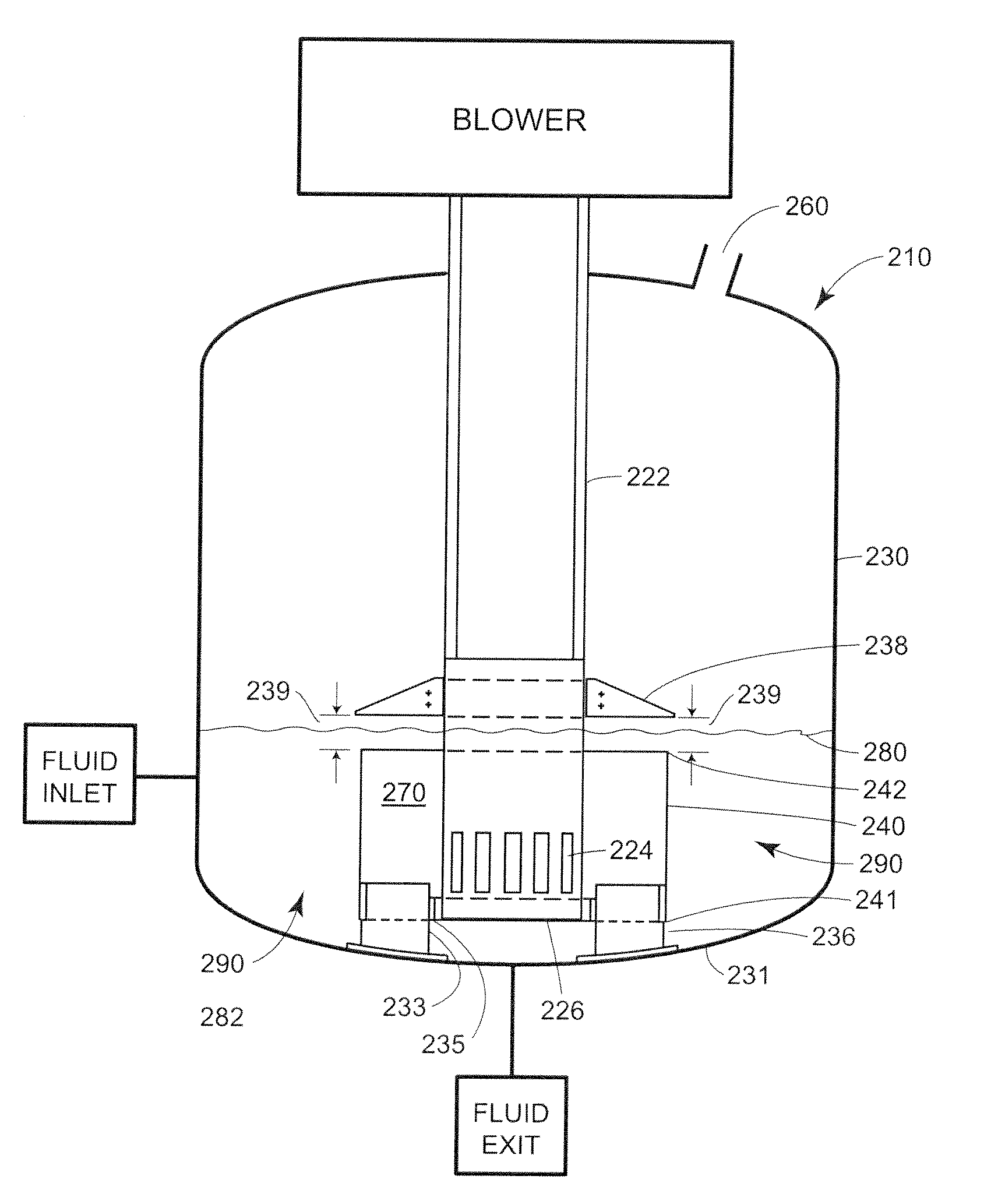
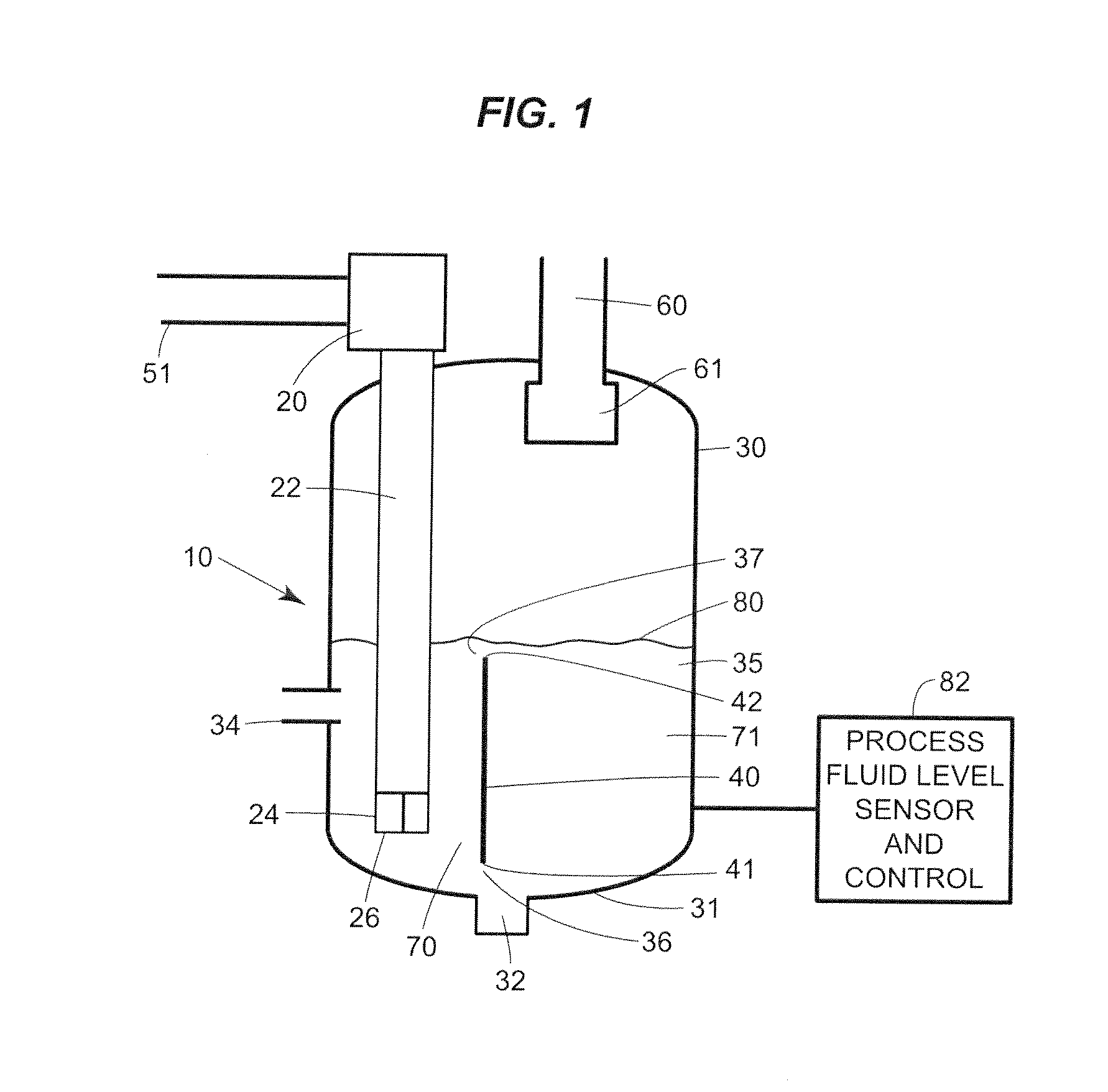
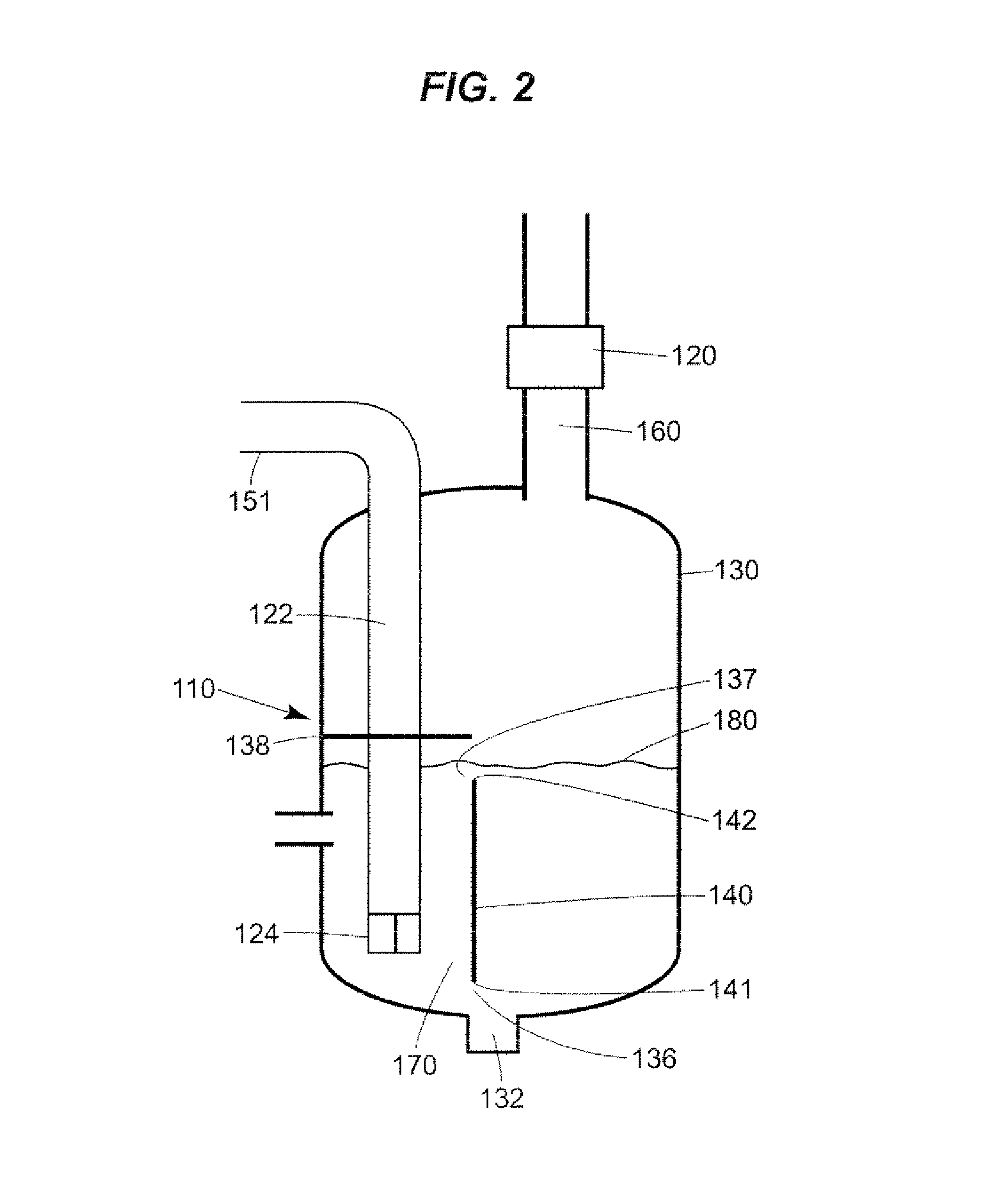
[0027]Referring to FIG. 1, a cooling tower 10, in the form of a submerged combustion gas evaporator, includes a blower 20 that provides gas under positive pressure to an evaporator vessel 30 through a gas supply Lube or gas inlet tube 22 having sparge or ...


PUM

PropertyMeasurementUnit
distanceaaaaaaaaaa
temperatureaaaaaaaaaa
heightaaaaaaaaaa

Abstract

A cooling tower includes an evaporator vessel, a gas delivery tube partially disposed within the evaporator vessel to deliver a gas into the evaporator vessel and a water inlet that provides water to the evaporator vessel at a rate sufficient to maintain a controlled constant level of water within the evaporator vessel. A weir is disposed within the evaporator vessel adjacent the gas delivery tube to form a first fluid circulation path between a first weir end and a wall of the evaporator vessel and a second fluid circulation path between a second weir end and an upper end of the evaporator vessel. During operation, gas introduced through the tube mixes with the water and the combined gas and fluid flow at a high rate with a high degree of turbulence along the first and second circulation paths defined around the weir, thereby promoting vigorous mixing and intimate contact between the gas and the water. This turbulent flow develops a significant amount of interfacial surface area between the gas and the water which leads to a more efficient and complete evaporation.

Description

FIELD OF THE DISCLOSURE[0001]The present disclosure relates generally to cooling towers, and more specifically, to evaporative or wet cooling towers.BACKGROUND[0002]Cooling towers of the evaporative type are used to cool water to levels that approach ambient air temperatures. Because the water discharged from cooling towers may be recycled back to the cooling tower from processes that apply the water for cooling purpose, cooling towers are most generally used for the purpose of conserving water resources. Common applications for the cooling water produced in cooling towers include removing heat from critical components or controlling the operating temperature of engines, electrical generators, refrigeration compressors (e.g., air conditioning) and a broad range of industrial processes across a broad spectrum of industries. Natural draft and mechanical draft cooling towers are the two types of cooling towers that are most commonly used in commercial service.[0003]As evaporative coole...

Claims


Application Information

Patent Timeline
Patent Type & Authority Patents(United States)
IPC IPC(8): B01F3/04
CPCB01D1/0058B01D1/14B01D1/305C02F1/10F28C3/06
Inventor DUESEL, JR., BERNARD F.RUTSCH, MICHAEL J.
Owner HEARTLAND TECH PARTNERS
Why Eureka
Try Eureka