Fuel filter device

a technology of fuel filter and filter body, which is applied in the direction of filtration separation, machines/engines, separation processes, etc., can solve the problems of difficult to constitute an adequate filter body, limit the number of filter materials overlaid, etc., and achieve the effect of improving the filtering precision of the filter body

Active Publication Date: 2012-03-20
NIFCO INC
View PDF77 Cites 25 Cited by
  • Summary
  • Abstract
  • Description
  • Claims
  • Application Information

AI Technical Summary

Benefits of technology

[0009]According to such filter device, by a single such multifunctional filter material, it is possible to capture dust having different particle sizes, from coarse dust to fine dust, respectively in different places in the thickness direction of this multifunctional filter material, and it is possible to adequately remove the dust from the fuel taken thereinto in a condition such that clogging of the filter body tends not to occur.
[0012]then it can be made such that such welding can be accomplished easily and adequately while minimizing the number of sheets of filter materials layered in the welded places.
[0013]If such multifunctional filter material is produced by air-laid method, then a filter material of nonwoven cloth having a smooth density gradient can be obtained comparatively cheaply, and it becomes easy to cheaply supply a filter device that has high filtering precision and tends not to clog.
[0015]Also, if a filter material produced by melt-blown method and having the average aperture size made smaller than the average aperture size of the multifunctional filter material is overlaid on the secondary side of such multifunctional filter material, then it is possible to constitute a filter device having long life, with the filter material made by melt-blown method by which it is easy to make the average aperture size small as a main filter, and said multifunctional filter material as a pre-filter, in a condition having minimized the burden on this main filter.
[0016]Also, if the filter material positioned on the innermost side of the filter body is made as a filter material formed by spun-bond method, then the filter body is given rigidity (stiffness) by such filter material positioned on the innermost side whereby it can be made easy to maintain the shape of the filter body.
[0018]By this invention, with the multifunctional filter material it is possible to accomplish to the extent possible improvement of filtering precision of the filter body constituting the filter device and long life without increasing the number of overlaid filter materials. As a result, it is possible to constitute the filter device easily and adequately, as well as cheaply.

Problems solved by technology

However, considering the manufacturing cost, and the like, of the filter body, there is a limit to the number of filter materials overlaid.
Also, because the number of filter materials at the places to be welded in order to have a bag-like shape increases as the number of filter materials overlaid becomes greater, it becomes difficult to constitute an adequate filter body by such welding.Patent Document 1: Japanese Unexamined Patent Application Publication No. 2005-48721

Method used


Image

  • Fuel filter device
  • Fuel filter device
  • Fuel filter device

Examples


Embodiment Construction

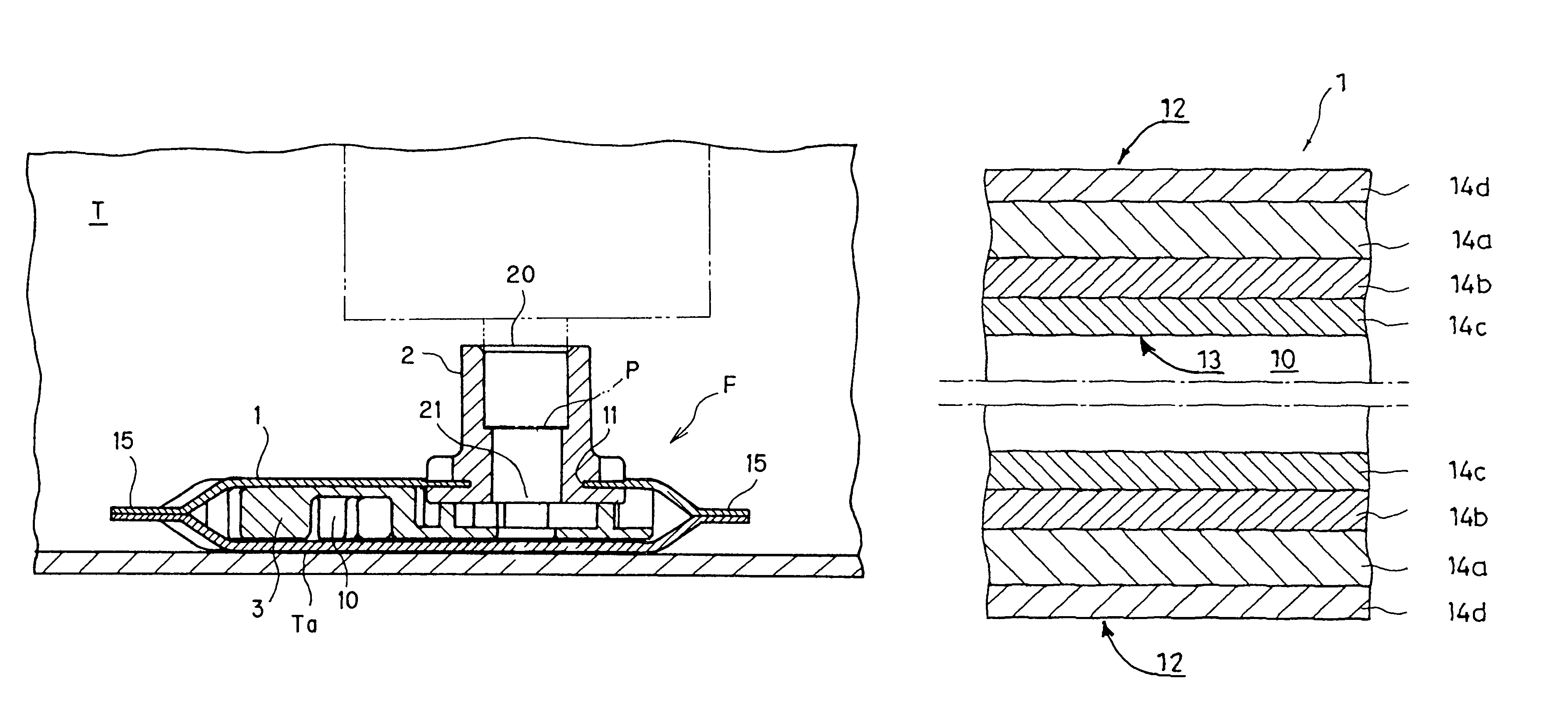
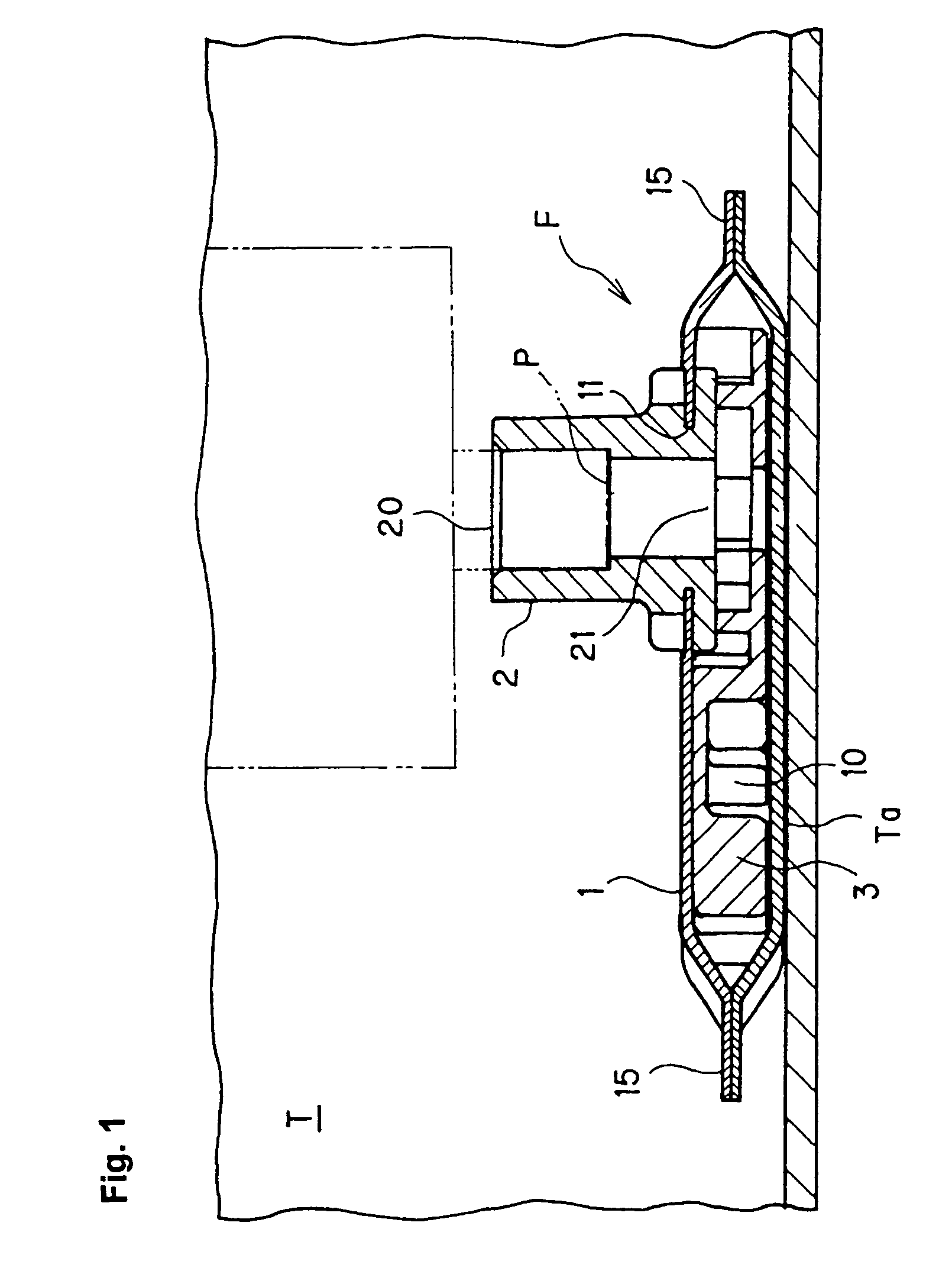
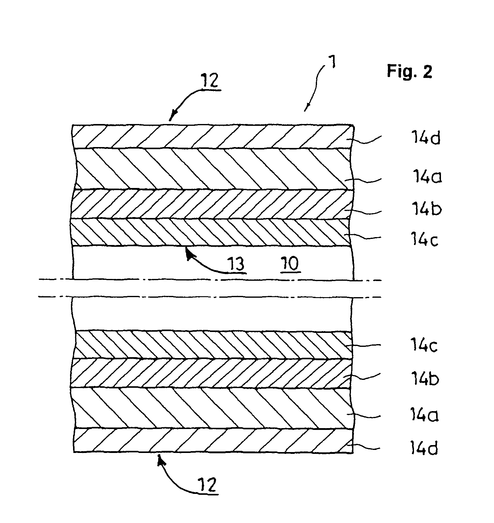
[0021]A preferred mode of working of this invention is explained below based on FIG. 1 and FIG. 2.

[0022]Here, FIG. 1 is a structural view showing the condition in which the filter device F is attached to the fuel intake port P inside the fuel tank T; also, FIG. 2 shows one example of the cross sectional structure of the filter body 1 constituting such filter device F. (In FIG. 2, only the cross sectional structure on the upper side and the lower side of the filter body 1 is represented, and the space forming member 3 held inside the filter body 1 is omitted.)

[0023]The fuel filter device F pertaining to this mode of working is attached to the fuel intake port P inside the fuel tank T of an automobile or motorcycle, or the like, so that water and foreign matter do not exit in the fuel sent to the internal combustion engine via such fuel intake port P.

[0024]Typically, such filter device F is attached to the fuel intake port P on an intake pipe having this fuel intake port P inside the ...


PUM

PropertyMeasurementUnit
porosityaaaaaaaaaa
aperture sizeaaaaaaaaaa
rigidityaaaaaaaaaa

Abstract

A filter device includes a bag-shape filter body. The filter device is attached in a manner such that an internal space of the filter body connects through to a fuel intake port in a fuel tank. The filter body includes two or more filter materials overlaying each other. At least one of the filter materials is configured so that a cross sectional area of its fuel passage is different between a primary side and a secondary side of the filter material so as to be a multifunctional filter material having a function of gradually capturing dust having different particle sizes.

Description

FIELD OF TECHNOLOGY[0001]This invention relates to an improvement of a fuel filter device to be attached to a fuel intake port in a fuel tank.BACKGROUND ART[0002]Fuel inside the fuel tank is sent to a side of the internal combustion engine through an intake pipe, and the like, disposed inside this fuel tank. A filter device is attached to the fuel intake port of such intake pipe in order to remove water from the fuel thus sent and to make it such that dust is not sent into the fuel pump. As such a filter device, there is one shown in Patent Document 1 disclosed by the present applicant.[0003]Inside the filter device of Patent Document 1, there is a bag-like filter body having an internal space which is made to connect through to the fuel intake port inside the fuel tank. Such filter body has two layers of filter materials made of nonwoven cloth produced by melt-blown method between a filter material on the outermost layer made of woven fabric mesh and a filter material on the innerm...

Claims


Application Information

Patent Timeline
Patent Type & Authority Patents(United States)
IPC IPC(8): B01D29/13B01D29/15B01D35/02F02M37/22
CPCB01D35/0273B01D39/1623B01D2201/188B01D2239/065F02M2037/228F02M37/50
Inventor OGOSE, KENSUKE
Owner NIFCO INC
Why Eureka
Try Eureka