Multistage variable reluctance motor/generator

a variable reluctance, multi-stage technology, applied in the direction of synchronous motors, magnetic circuit shapes/forms/construction, instruments, etc., can solve the problems of large torque ripple effects in the torque output of the machine, low torque available, structural distortion of the motor casing, etc., to improve the torque production capability and overall operating efficiency, and reduce the overall complexity. , the effect of reducing the complexity

Active Publication Date: 2012-03-20
SUNCO INVESTMENTS
View PDF47 Cites 17 Cited by
  • Summary
  • Abstract
  • Description
  • Claims
  • Application Information

AI Technical Summary

Benefits of technology

[0020]The present invention provides additional benefits in design technique, construction, control and performance over conventional multi-stage switched reluctance motor devices. Building on a motor having a plurality of stages, with the rotor and stator sections of each stage arranged with an equal number of poles, the invention utilizes advanced design techniques to optimize the arrangement, construction, performance, cooling and control of the invention. The simplicity of the invention and its associated electromagnetic structure allows for the development of a specialized and highly advanced computer modeling design technique to both optimize the design elements of the invention and to accurately predict machine performance over a wide variety of design needs. The advantage of the invention design technique resides in the ability that each component of the invention can thereby be accurately modeled as to its physical, electrical, thermal and magnetic properties so that the overall performance of the invention can be optimized for each application.
[0021]Accordingly, the invention incorporates a series of advancements in its construction that both reduce its overall complexity while significantly improving its torque producing capabilities and overall operating efficiencies. The invention employs a multiplicity of stages, each stage having stator and rotor sections with an identical number of poles, wherein individual stage stator poles and corresponding stage rotor poles form individual pole pairs that are all in identical alignment. In contrast with the Richardson patent, the invention contains a number of significant construction improvements. The stator section of each stage is formed from a laminated magnetic element forming both the back iron and the pole structures of the stator section. In one preferred embodiment, the stator section of each stage comprises a monolithic annular laminated stator section. The electromagnetic coils affixed to each stator pole are simple machine wound devices that are capable of being mass-produced and easily assembled within the machine.
[0022]As the coils affixed to the stator poles of each stage are energized in unison, the electrical power distribution within the machine is simple and straight forward. The invention further reduces the sizing of the electrical power distribution system within each stage by splitting the power supply into two halves with each branch feeding a portion of the electrical energy to a portion of the allotted number of coils per stage. During operation, the voltages in adjacent coils in a given stage are identical; therefore, there is no potential for a short between adjacent coils as is common with other electric motor arrangements. The stator construction particular to the invention provides for a smaller, simpler and lighter weight construction than is the case in the Richardson patent. As well, the construction of the invention stator provides for a more effective means for the removal of heat from the device, which in turn adds to the compactness of the invention.
[0023]Each rotor stage of the invention is also formed from a laminated magnetic element containing the outwardly directed pole structures and shaft connection means as required by the performance characteristics of the machine. In a preferred embodiment, each rotor stage comprises an annular monolithic laminated magnetic element. The rotor poles of each stage are radially displaced, one stage to the other along the axis of the invention thereby insuring that at any time, at some combination of plurality of stages and stage rotor pole displacement angles, one stage of rotor poles will be correctly aligned with its corresponding stage of stator poles forming a multiple of air gaps between the stage pole pairs such that when the stator coils are energized, a local magnetic circuit is completed drawing all of the correctly aligned rotor stage poles into alignment with the corresponding stator stage poles resulting in rotation of the rotor assembly and the transfer of torque to the rotor shaft. Once in rotation, successive stages will be in correct mechanical alignment to permit the electric power supply control algorithm and electric circuitry elements of the present invention to advance the electrical energy to the next stage of the invention to insure a smooth and continuous transfer of torque and rotational motion to the rotor shaft in a stage-to-stage manner. Conversely, the correct alignment of the stage pairs when rotated by an external mechanical energy source, combined with a simultaneous low level energizing voltage applied to the corresponding stator rotor coils will result in a magnetic field being established between the pole pair which will result in the generation of a much larger current in the stage stator rotor coils, which when combined with the current produced from each successive stage of rotor coils will result in a continuous power generation capability as long as the external mechanical power is applied to the rotor shaft.
[0024]Particular to the present invention is the skewing of the stage rotor poles along the axis of rotation of the individual rotor poles of each stage. In the course of assembly on a custom assembly jig, each successive lamination that in total number make up the magnetic mass of each rotor stage, the laminations are displaced radially one to the other such that the totality creates a skew of the stage rotor poles. In skewing the rotor poles at an angle to the stator poles, an overlap is created in the air gap between the stage pole pairs causing a more gradual decrease to the reluctance in the air gap between the pole pairs on transferring energy to the individual stage stator poles than is found with a parallel alignment of the stage stator and rotor pole pairs. In a similar manner, a gradual tapering off of the reluctance energy in the air gap is created as the stage rotor poles leave the influence of the magnetic fields of the corresponding energized stage stator poles. In operation the skewed rotor pole angles demonstrate a further reduction in the energy levels of the torque ripple / current ripple created when shifting the electrical / mechanical energy from one stage to the next.
[0025]The radius of the rotor, the number of poles, the length of the poles, the width of the poles, the thickness of the back iron, the number and thickness of the laminations, the size and shape of the electromagnetic coils are all determined by the invention design techniques. Input to the design technique includes, but is not limited to: desired output torque / current, desired motor / generator speed range, size limiting spatial constraints, input / output voltage, input / output current.

Problems solved by technology

As a consequence of having only one pole pair in the correct position at any given time (due to the different pitch between the number of stator and rotor poles) during the energizing sequence, relatively low torque is available.
Manufacturers therefore will normally oversize switched reluctance motors relative to their steady-state operation performance leading to structural distortion of the motor casing, vibration, noise, large torque ripple effects in the torque output of the machine and low motor efficiency throughout the motor's operating range.

Method used


Image

  • Multistage variable reluctance motor/generator
  • Multistage variable reluctance motor/generator
  • Multistage variable reluctance motor/generator

Examples


Embodiment Construction

[0056]The present invention will be further understood by reference to the following non-limiting example.

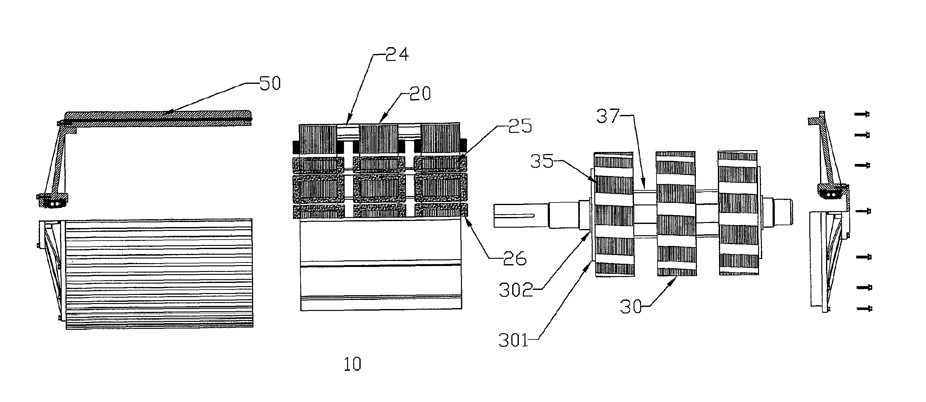
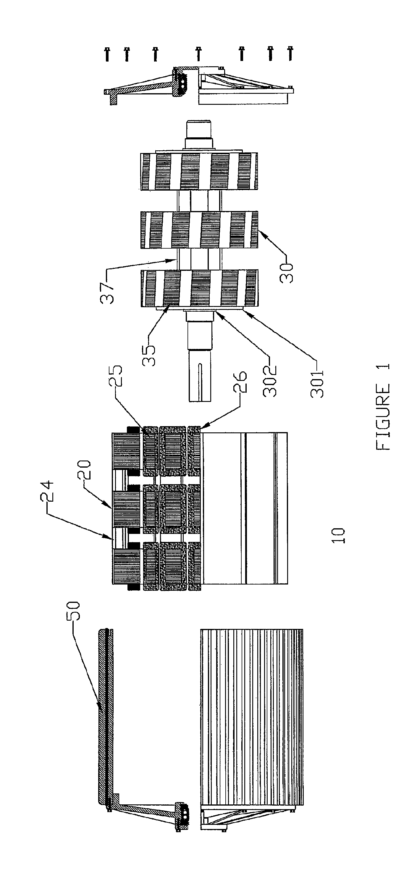
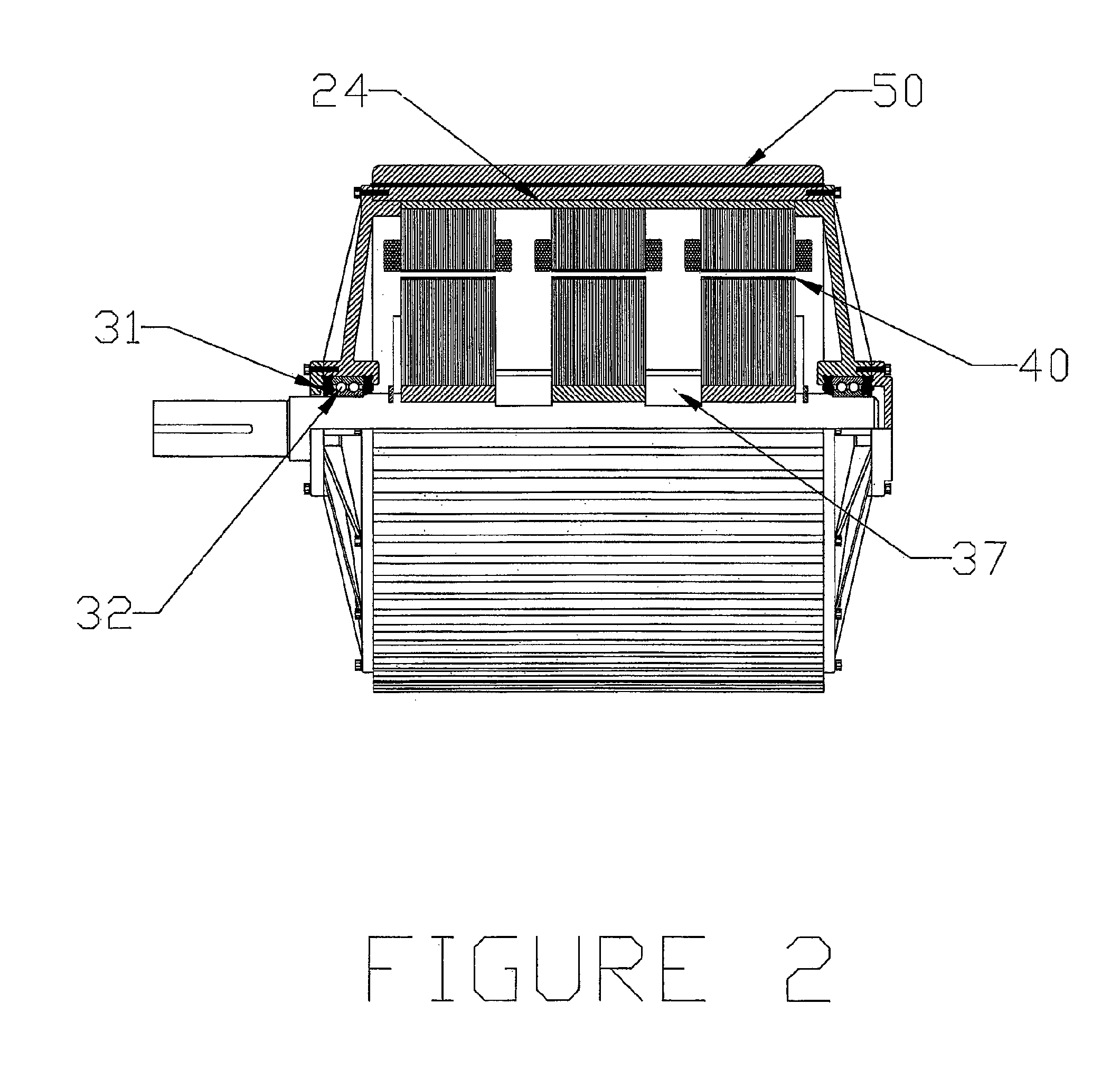
[0057]Referring to the drawings that are provided to illustrate preferred embodiments of the invention only, and not for the purpose of limiting same, FIGS. 1 to 5 illustrates a version of the invention, which having motoring / generating capabilities is suitable for use as a traction motor in large transport vehicles such as automobiles, highway and off-road trucks, buses, mobile mining equipment, marine propulsion systems, locomotive propulsion systems in which regeneration is a positive design attribute to reduce the energy consumption of these drive systems. As heavy duty industrial motors only, the invention can find a multiple of uses in such heavy duty service as pump drives, compressor drives, conveyor drives; while as heavy duty generators only the invention will be ideally suited for use in wind turbines, exhaust turbo generators, water turbines, stand-by power generatio...


PUM

PropertyMeasurementUnit
radial angleaaaaaaaaaa
timeaaaaaaaaaa
physicalaaaaaaaaaa

Abstract

A compact, rugged, variable reluctance, variable speed, electric motor capable of producing high torque at high electrical energy conversion efficiencies is provided. The present invention provides for a multi-stage motor design having a number of discreet rotor and stator elements on a common shaft. This configuration provides for the simplest of magnetic structures and produces a powerful magnetic flux modelling design technique that is used to further optimize the motor design and subsequent control logic. Thermal mapping of the magnetic mass provides for advanced cooling techniques that are used to ensure long in-service life in the most extreme of industrial applications. The electric motor inherently provides low vibration thereby greatly reducing noise; low turn to turn voltage potentials thereby eliminating costly phase to phase shorting potential; efficient motor operation through the reduction in switching and copper losses in both the machine and its control system.

Description

FIELD OF THE INVENTION[0001]The present invention relates to the field of variable speed electric motors. The present invention more particularly relates to the design, construction, cooling and control of multi-stage variable reluctance machines operating efficiently, both as high torque electric motors and as efficient current generators.BACKGROUND OF THE INVENTION[0002]The present invention relates to the construction of electro-mechanical devices, most commonly known as switched reluctance motors. These motors can translate electrical energy into power and torque through the use of electromagnetic structures built around a fixed stator and an internal rotating rotor. In general, the stator of the prior art is generally comprised of a plurality of discreet lobes or poles, which extend inwardly towards the rotor. The associated rotor is also constructed of magnetic materials having a plurality of discreet poles that are constructed to extend outwardly toward the stator poles. To e...

Claims


Application Information

Patent Timeline
Patent Type & Authority Patents(United States)
IPC IPC(8): H02K17/42
CPCH02K11/048H02K19/06H02P25/082H02K19/103H02K16/00Y10T29/49009Y02E10/725H02P25/0925Y02E10/72
Inventor DAVIS, JOHN ADAVIS, IAIN CHURZOOK, FEISAL A
Owner SUNCO INVESTMENTS
Why Eureka
Try Eureka