
Remote battery charging system with dynamic voltage adjustment and method of use

a charging system and battery technology, applied in electrical equipment, transportation and packaging, electric vehicles, etc., can solve the problems of charging being disabled, not as good as an ideal four-wire sensing system, etc., and achieve the effect of increasing the overall safety and reliability of the system or remaining unchanged

Inactive Publication Date: 2012-03-20
GALVION POWER SYST INC
View PDF5 Cites 17 Cited by
  • Summary
  • Abstract
  • Description
  • Claims
  • Application Information

AI Technical Summary

Benefits of technology

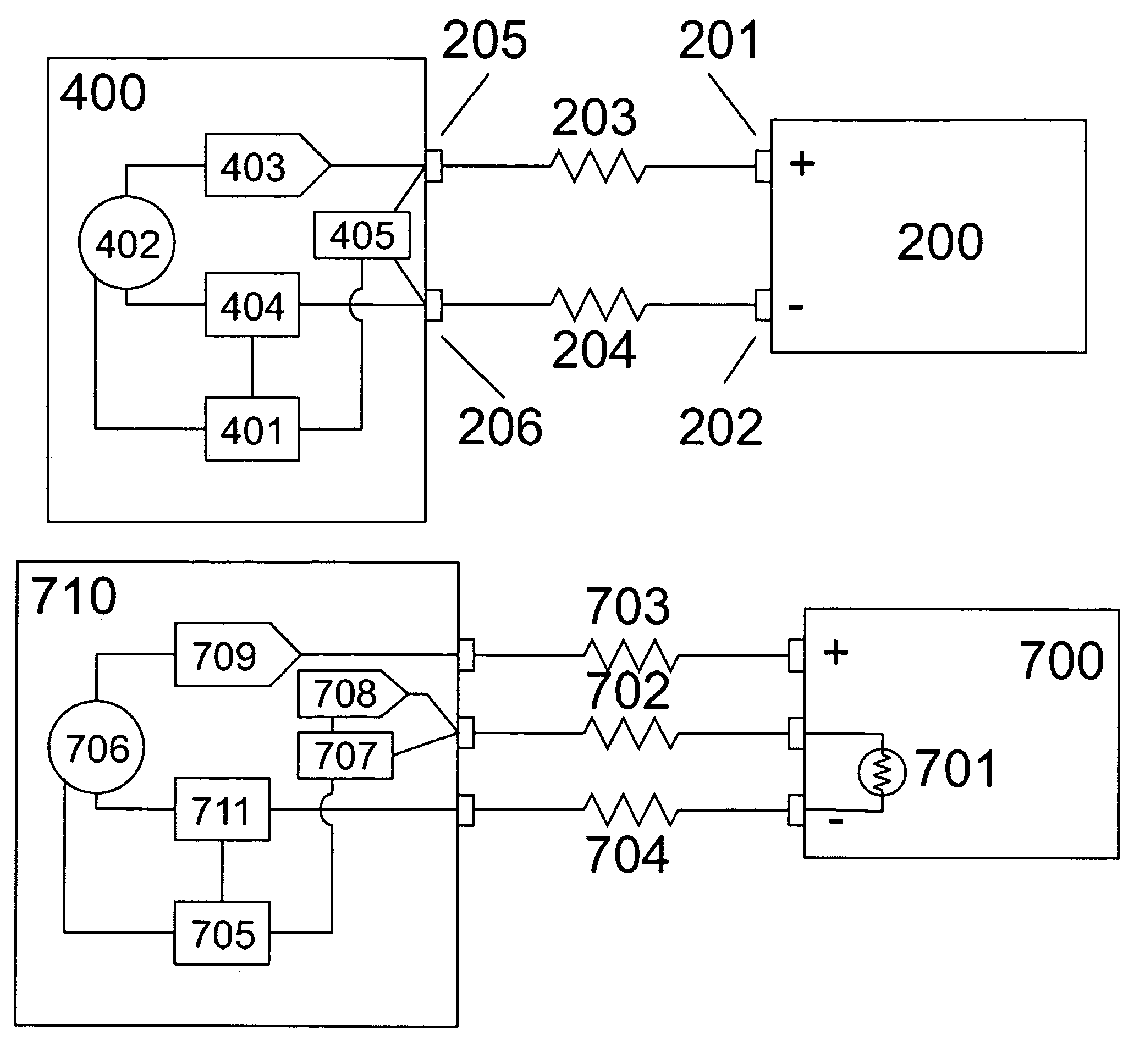
"The invention provides a system for improving the performance of a dumb charging system that connects to a battery through only two long wires, with no remote sensing of any kind. The system uses a voltage translator circuit or a microprocessor to monitor the output current or voltage of the charging circuit and uses this signal to modify the output voltage with a variable offset to compensate for voltage loss in the wires and connectors leading to the battery. This compensation is fixed at a compromise level and can be adjusted dynamically to closely match the performance and control of a four-wire battery charger system. The system also uses a single wire for compensation, which is safer than a dedicated sense wire, and a third wire connection that is normally used for temperature monitoring to further improve charging time and voltage accuracy. The invention provides a more efficient and accurate charging system for batteries."

Problems solved by technology

In this system, the amount of compensation must be less than or equal to the expected requirements of the wires and connectors leading to the battery, but the precise value cannot be determined, and therefore the compensation will not be as good as an ideal four-wire sensing system.
In the case of a standard 10K NTC Thermistor, an open wire will be interpreted as an extremely cold battery which will result in charging being disabled.

Method used


Image

  • Remote battery charging system with dynamic voltage adjustment and method of use
  • Remote battery charging system with dynamic voltage adjustment and method of use
  • Remote battery charging system with dynamic voltage adjustment and method of use

Examples


Embodiment Construction

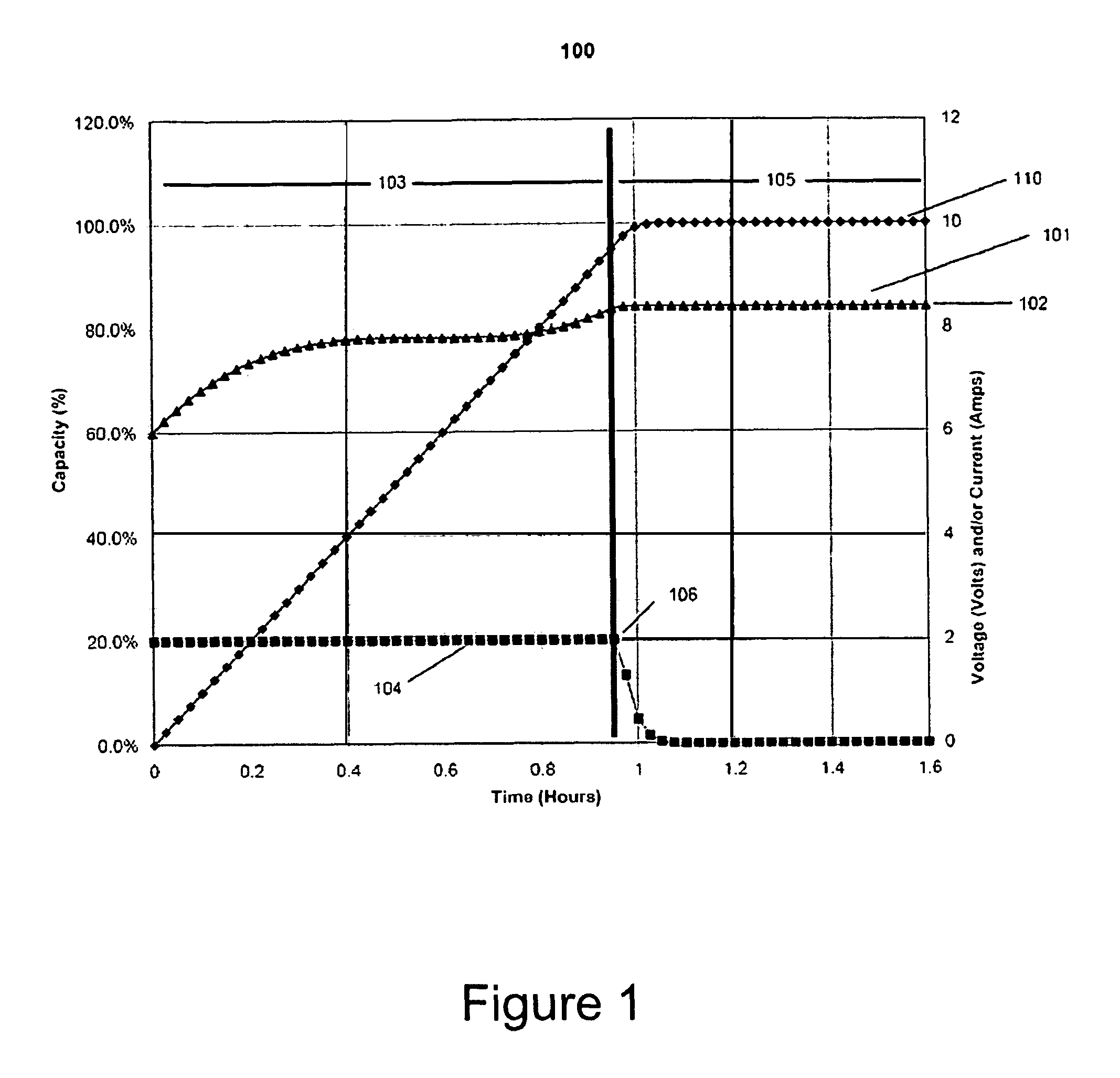
[0030]Referring to FIG. 1, a graph (100) showing ideal charger performance when connected to a lithium battery. In this case the output voltage Vo (101) of the charger is exactly the same as the voltage present on the battery terminals VBatt (101). In the case of a two-cell Lithium Polymer battery where the end-of-charge voltage is 8.4 volts (102), the desired maximum charge rate is 2 amps and the battery capacity is 2 amp-hours, the graph shows what characteristics make this an ideal charger.

[0031]The graph is divided into two sections. In the Constant Current (CC mode) section (103), the battery voltage is lower than 8.4 volts so the charge current (104) will be exactly 2 amps. Once the battery reaches 8.4 volts the system enters Constant Voltage (CV mode) (105). In an ideal case a “knee” is formed (106) in the graph where the charging current Io immediately and rapidly begins to fall. This happens at the point where the battery voltage (101) reaches 8.4 volts. The total charge ti...


PUM


Abstract

In a remote battery charging system comprising a charging circuit there is always a voltage loss due to inherent resistances in the system from such things as connectors and conductors. These resistances create voltages losses in the system such that charging time are increased substantially. The present invention compensates for voltage losses on the system by generating a dynamic adjustment voltage over the charging period. A voltage translator circuit is used to measure charging circuit output voltage and current over a plurality of incremental time periods during the charging period an calculate a signal proportional to changes in output voltage and current over the incremental time period. The signal is then applied to the charging circuit to offset any voltage losses.

Description

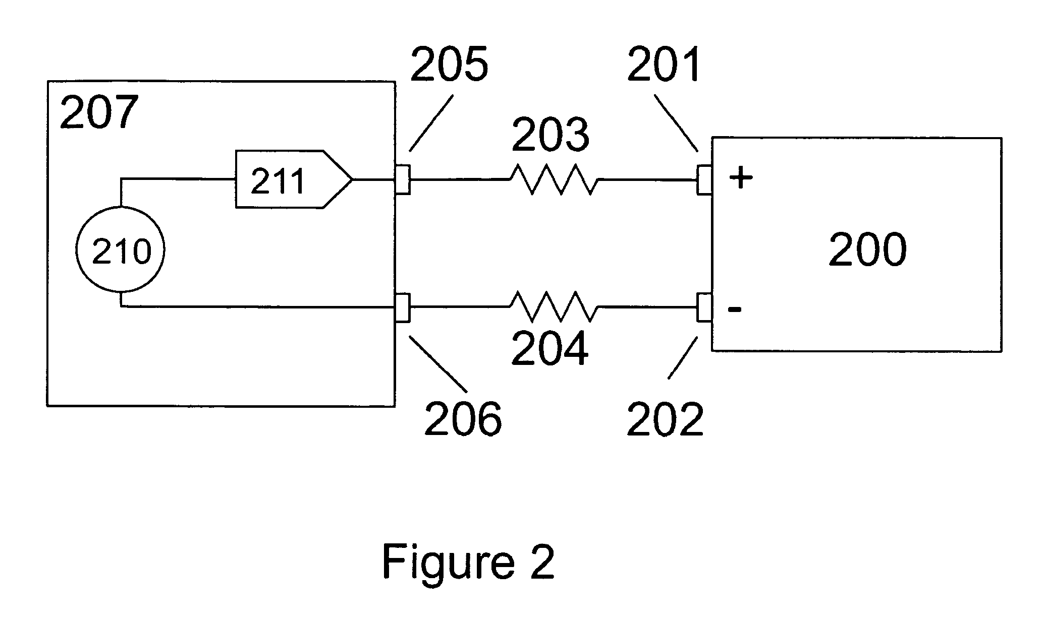
BACKGROUND OF THE INVENTION[0001]Different rechargeable battery technologies require different charging techniques. A popular battery charging technology is called CCCV or Constant Current Constant Voltage charging. This charging technique uses a controlled current to recharge the battery during the first phase of charging. As the battery nears fully charged the charger voltage reaches a point where it is limited and the current is allowed to fall. This method of charging is most commonly used in ion-exchange systems such as Lithium Ion based batteries.[0002]Systems currently in use fall into two broad categories, hardware based “dumb” chargers which use discrete circuitry to control the CCCV system, or “smart” chargers which communicate with the battery through a digital communication path, or use four-wire voltage sensing at the battery terminals to precisely set the current or voltage outputs from the charge system.[0003]Dumb chargers have the advantage that they are very low cos...

Claims


Application Information

Patent Timeline
Patent Type & Authority Patents(United States)
IPC IPC(8): H02J7/00H02J7/04H02J7/16
CPCH02J7/0073H02J7/0071
Inventor CARKNER, STEVE
Owner GALVION POWER SYST INC
Learn More