Front-end architecture of RF transceiver and transceiver chip thereof

a radio frequency and transceiver technology, applied in transmission, multiple-port network, electrical apparatus, etc., can solve the problems of unnecessary power consumption, low yield of gaas process, and still possess some drawbacks

Active Publication Date: 2012-03-20
MEDIATEK INC
View PDF5 Cites 19 Cited by
  • Summary
  • Abstract
  • Description
  • Claims
  • Application Information

AI Technical Summary

Problems solved by technology

If the antenna ANT cannot match impedance with the receiver unit 161 or with the transmitter unit 163 in either mode, the input signals are reflected to the point of origin, causing unnecessary power consumption.
Although GaAs materials are suitable to high-frequency circuits, they still possess some drawbacks.
For example, the yield of the GaAs process is relatively low and the manufacturing cost thereof is relatively high.
In addition, such kind of technology cannot implement a system-on-chip structure, thus causing additional package and test expenses.
Those additional components occupy a large space and thus increase the materials cost.

Method used


Image

  • Front-end architecture of RF transceiver and transceiver chip thereof
  • Front-end architecture of RF transceiver and transceiver chip thereof
  • Front-end architecture of RF transceiver and transceiver chip thereof

Examples


Embodiment Construction

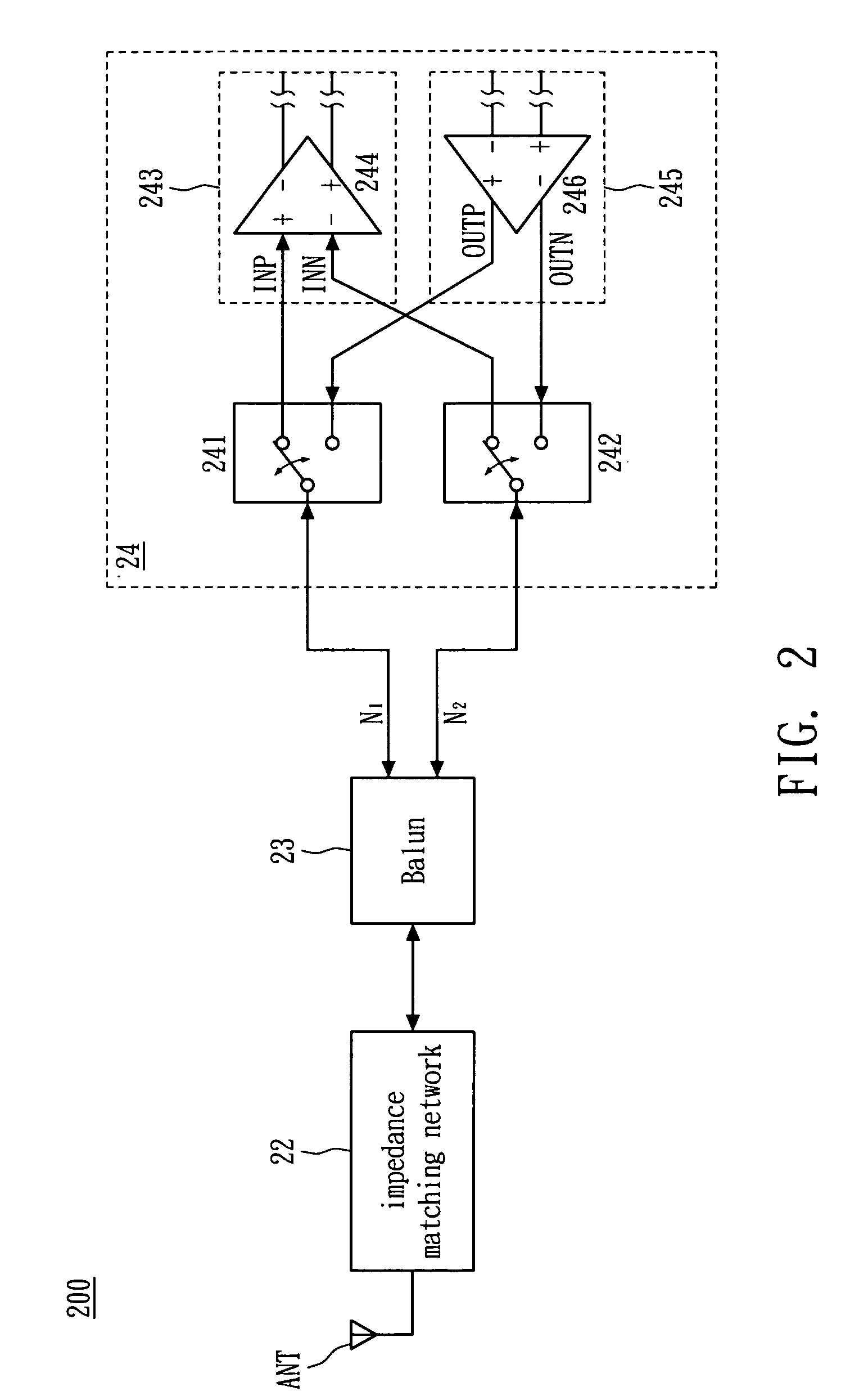
[0018]FIG. 2 shows a structure of a front-end circuit of an RF transceiver in accordance with one embodiment of the present invention. Referring to FIG. 2, the front-end circuit 200 is disposed on a printed circuit board, and includes an antenna ANT, an impedance matching network 22, a balance to unbalanced transformer (balun) 23 and a transceiver chip 24. The transceiver chip 24 includes a first transmit / receive (T / R) switch 241 and a second T / R switch 242, a receiver unit 243 and a transmitter unit 245. The receiver unit 243 includes a low noise amplifier 244, which receives a differential input signal between a first input terminal INP and a second input terminal INN and generates a differential output signal. The transmitter unit 245 includes a power amplifier 246, which receives a differential input signal and generates a differential output signal between the first output terminal OUTP and the second output terminal OUTN. The first T / R switch 241 and the second T / R switch 242 ...


PUM


Abstract

An RF front-end architecture is operated in either a transmitting or a receiving mode. The RF front-end architecture comprises an antenna, an impedance match network, a balun and a transceiver chip. The transceiver chip comprises first and second transmit / receive (TR) switches, a transmitter, and a receiver. Because two TR switches are integrated into the chip, the printed circuit board area, BOM cost and pin count of the transceiver chip can be greatly reduced.

Description

BACKGROUND OF THE INVENTION[0001]1. Field of the Invention[0002]The present invention relates to a circuit structure, and more particularly, to a highly-integrated front-end architecture of a radio frequency (RF) transceiver and the transceiver chip thereof.[0003]2. Description of the Related Art[0004]FIG. 1 shows a conventional front-end architecture of an RF transceiver. As shown, the front-end architecture 100 of an RF transceiver is disposed on a printed circuit board, which includes an antenna ANT, a transmit / receive (T / R) switch 11, a first impedance matching network 12 and a second impedance matching network 13, a first balance to unbalanced transformer (balun) 14 and a second balun 15, a receiver unit 161 and a transmitter unit 163, wherein the receiver unit 161 and the transmitter unit 163 are integrated in a transceiver chip 16. The receiver unit 161 includes a low noise amplifier (LNA) 162, which receives an RF signal through the antenna ANT. The transmitter unit 163 incl...

Claims


Application Information

Patent Timeline
Patent Type & Authority Patents(United States)
IPC IPC(8): H01P1/10H03H7/46
CPCH03H7/38H03H7/42H04B1/48H04B1/18H04B1/0458
Inventor CHU, CHUN HSUEH
Owner MEDIATEK INC
Why Eureka
Try Eureka