

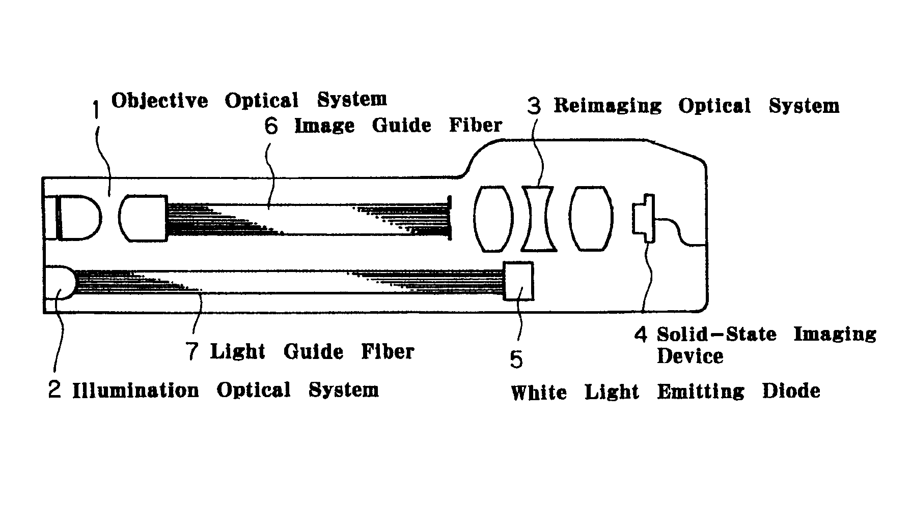
Reimaging optical system and endoscope using the same
a technology of which is applied in the field of reimaging optical system and endoscope using the same, can solve the problems of reducing the magnification of a reimaging optical system, affecting the magnification of the endoscope, so as to improve the magnification and improve the performan
- Summary
- Abstract
- Description
- Claims
- Application Information
AI Technical Summary
Benefits of technology
Problems solved by technology
Method used
Image

Examples
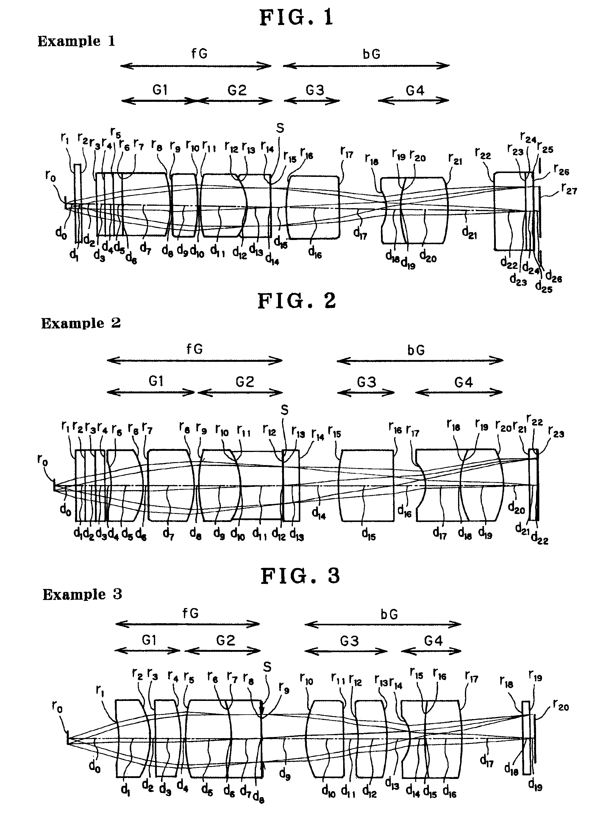
example 1
[0072]
Nordneνe0∞0.61(object plane)1∞0.41.5182563.932∞113∞0.561.5509845.494∞0.561.5509845.495∞0.561.5509845.496∞0.0317∞31.8881540.528−6.3530.219∞1.51.5182563.9310−12.3040.21119.37431.7323454.4512−3.3750.011.5119362.7413−3.3751.51.8126425.2214∞0.03115∞0.971(Stop)167.06533.4371.7323454.4517∞3.122118−2.27180.91.8394542.47195.84420.011.5119362.74205.84423.1431.8550423.5921−6.33272.995122∞21.5182563.9323∞0.011.5119362.7424∞0.51.5018663.8925∞0.021.5219762.7426∞0.37127∞(Image plane)
example 2
[0073]
Nordneνe0∞1.41(object plane)1∞0.631.5509845.492∞0.631.5509845.493∞0.631.5509845.494∞0.3515−6.88121.8881540.526−4.40.317∞2.81.5182563.93831 6.4640.3197.8252.61.7323454.4510−4.5170.011.5119362.7411−4.5172.61.8126425.2212∞0.031(Stop)13∞11.5156474.7414∞2.511515.0223.51.7323454.4516∞2117−2.1672.21.8394542.47185.3530.011.5119362.74195.3532.71.8126425.2220−5.3531.6121∞0.51.5018663.8522∞0.021.5219762.7423∞(Image plane)
example 3
[0074]
Nordneνe0∞3.51(object plane)1−5.93421.8881540.522−4.62230.313∞1.71.5182563.934−9.2280.3159.290431.7323454.456−8.68840.011.5119362.747−8.688421.9342918.748∞0.0319∞2.91(Stop)105.76032.51.7323454.4511∞1112−9.17021.951.8126425.2213−9.28721.5114−2.414911.8394542.471514.14450.011.5119362.741614.14452.51.8126425.2217−14.14454118∞0.51.5182563.9319∞0.35120∞(Image plane)
PUM
 Abstract
Description
Claims
Application Information