
Creation and transmission of part of protocol information corresponding to network packets or datalink frames separately

a technology of protocol information and datalink frame, applied in the direction of digital transmission, data switching network, instruments, etc., can solve the problems of network slowdown, overhead and logic for separating the data portion and the header portion, and the loss of packets of switches, so as to reduce or avoid network congestion

Active Publication Date: 2012-03-20
GEORGE GEORGE MADATHILPARAMBIL +2
View PDF7 Cites 0 Cited by
  • Summary
  • Abstract
  • Description
  • Claims
  • Application Information

AI Technical Summary

Benefits of technology

"The present invention relates to a method for reducing network congestion and improving efficiency in transmitting data packets. The invention involves creating and transmitting separate protocol information from the data packet, called STPI, which helps to avoid network congestion. The STPI contains all the necessary information for the network to forward the data packet to the destination. The method also allows switches to optimize resource usage and improve efficiency in forwarding packets. The invention can be used in various data transmission protocols and networks."

Problems solved by technology

This can lead to switches dropping large number of packets, nodes retransmitting the dropped or lost packets and network slowing down.
This method has a disadvantage that overhead and logic for separating the data portion and the header portion and then combining the header portion and the data portion before transmission is required.
This method also can not consolidate headers from more than one packet for transmission to the next node or delay packet arrival if the destination path of the packet is congested and therefore, can not avoid congestion.
This method can not consolidate headers from more than one packet for transmission to the next node or delay packet arrival if the destination path of the packet is congested and therefore, can not avoid congestion.
This method has a disadvantage that overhead and logic for separating the data portion and the header portion is required.
This method can not consolidate headers from more than one packet for transmission to the next-node or delay packet arrival if the destination path of the packet is congested and therefore, can not avoid congestion.
This method has a disadvantage that switches need to identify messages with common destination node and additional logic to remove header and add label.
This method can not delay packet arrival if the destination path of the packet is congested and therefore, can not avoid congestion.

Method used


Image

  • Creation and transmission of part of protocol information corresponding to network packets or datalink frames separately
  • Creation and transmission of part of protocol information corresponding to network packets or datalink frames separately
  • Creation and transmission of part of protocol information corresponding to network packets or datalink frames separately

Examples


Embodiment Construction

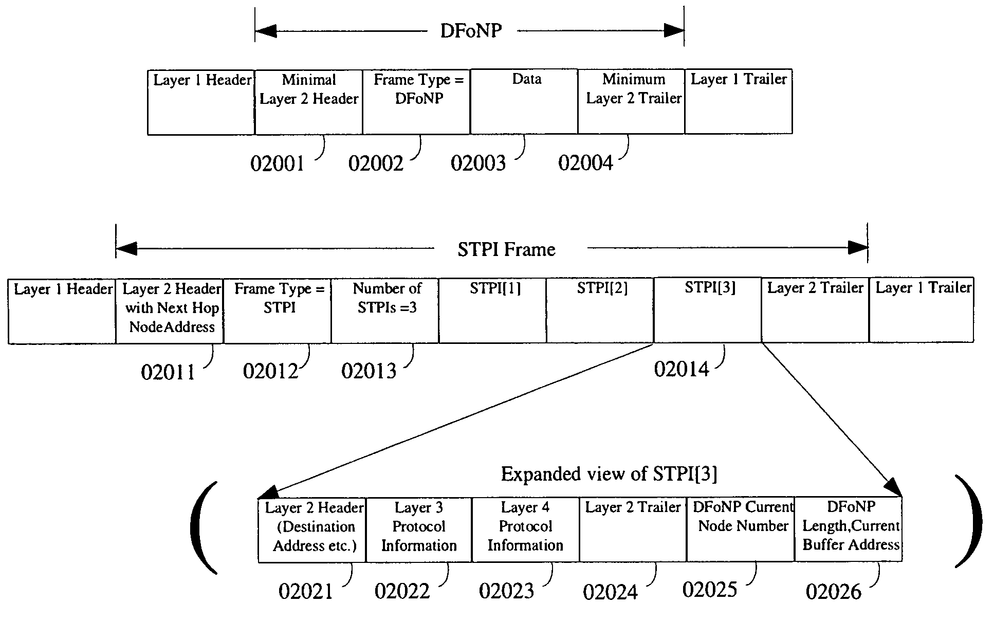
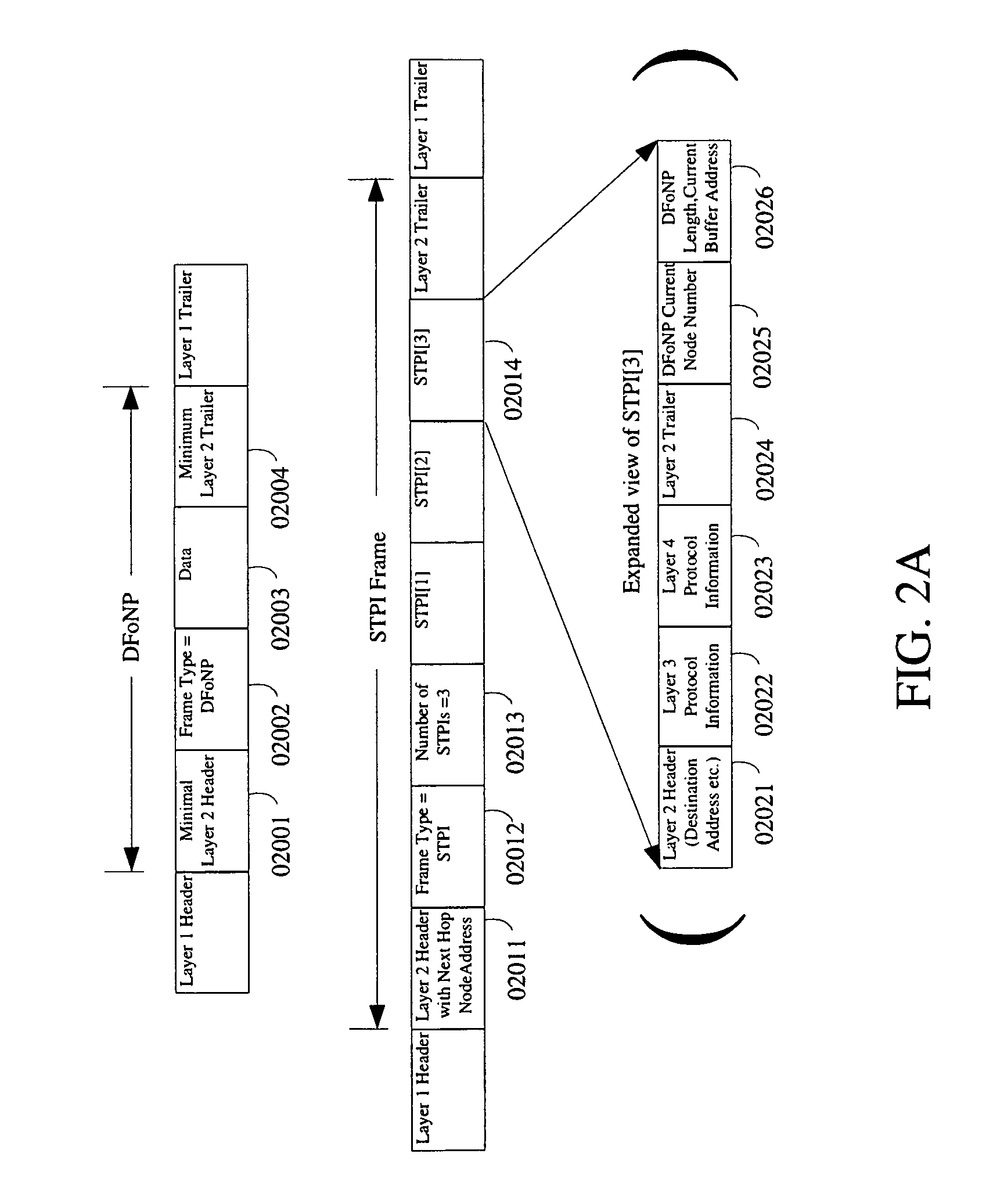
[0057]There are a very large number of design options with network component designers with respect to the format of DFoNP, STPI and STPI frame / packet. FIG. 2 illustrates some examples of different formats in which the STPI and the corresponding DFoNP can be created adhering to this invention. The layer 2, layer 3, and layer 4 information that may be present in the DFoNP and STPI may or may not be mutually exclusive and is dependent on specific format or formats of STPI and DFoNP supported by switches and endnodes. Each network will employ only few STPI / DFoNP formats (preferably, as few as 1-3), one each for a subtype of a packet or a frame. Preferably, a network may employ only one format for STPI and one format for DFoNP to reduce complexity in switches and endnodes. STPI should have enough information for the switch to find the port for the next hop.[0058]i) FIG. 2A illustrates example formats for DFoNP, the corresponding STPI and an STPI frame which contain STPIs. All layer 2 02...


PUM


Abstract

Datalink frames or networking packets contain protocol information in the header and optionally in the trailer of a frame or a packet. We are proposing a method in which part of or all of the protocol information corresponding to a frame or a packet is transmitted separately in another datalink frame. The “Separately Transmitted Protocol Information” is referred to as STPI. The STPI contains enough protocol information to identify the next hop node or port. STPI can be used avoid network congestion and improve link efficiency. Preferably, there will be one datalink frame or network packet corresponding to each STPI, containing the data and the rest of the protocol information and this frame / packet is referred to as DFoNP. The creation of STPI and DFoNP is done by the originator of the frame or packet such as an operating system.

Description

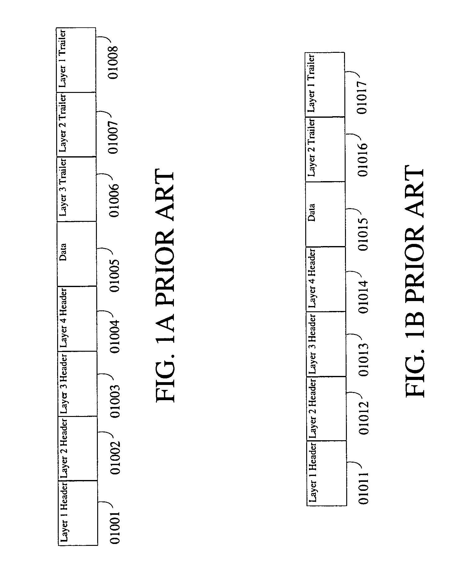
BACKGROUND OF THE INVENTION[0001]The present invention relates to efficient transfer of datalink frame or network packets in a “custom” network. The network is “custom” as all switches and end nodes need to create or process datalink frames or data packets of special formats.[0002]The OSI, or Open System Interconnection, model defines a networking framework for implementing protocols in seven layers. Most networking protocols do not implement all seven layers, but only a subset of layers. For example, TCP and IP protocol corresponds to layers 4 (TCP) and 3 (IP) respectively. Network packets contain protocol layer information corresponding to the packet. For example, a TCP / IP packet contains a header with both TCP and IP information corresponding to the packet.[0003]The physical layer (layer 1) specifies how bits stream is created on a network medium and physical and electrical characteristics of the medium. The datalink layer (layer 2) specifies framing, addressing and frame level e...

Claims


Application Information

Patent Timeline
Patent Type & Authority Patents(United States)
IPC IPC(8): H04L12/28H04L12/56H04L45/74
CPCH04L69/324H04L69/32G06F13/4022G06F13/4282H04L47/125H04L47/24H04L49/25H04L45/74
Inventor GEORGE, GEORGE MADATHILPARAMBILGEORGE, SUSANTHOMAS, MAMMEN
Owner GEORGE GEORGE MADATHILPARAMBIL
Learn More