Position detection apparatus and medical-device-position detection system

a detection system and position detection technology, applied in the field of position detection apparatus and medialapparatusposition detection system, can solve the problems of increasing the intensity of alternating magnetic field, and achieve the effect of improving the accuracy of the position detection of the object to be detected, and high amplification of the position detection apparatus

Active Publication Date: 2012-03-20
OLYMPUS CORP
View PDF8 Cites 10 Cited by
  • Summary
  • Abstract
  • Description
  • Claims
  • Application Information

AI Technical Summary

Benefits of technology

[0011]In Non-Patent Document 1, a position detection system including an excitation coil for generating an alternating magnetic field, an LC resonance magnetic marker for generating an induced magnetic field by receiving the alternating magnetic field, and a detecting coil for detecting the induced magnetic field are disclosed. According to this position detection system, since the LC resonance magnetic marker resonates at a predetermined frequency depending on additional capacitance and parasitic capacitance, by setting the frequency of the alternating magnetic field to the predetermined frequency, the intensity of the induced magnetic field can be significantly increased compared to that of other frequencies, and thus, the detection efficiency increases.
[0041]Since the alternating magnetic field can be more easily canceled out at the position of the magnetic-field sensor by positioning the reversed-phase-magnetic-field generator in the vicinity of the magnetic-field sensor, the amplification of the position detection apparatus can be set high. Thus, it is advantage in that the position detection accuracy can be improved.

Problems solved by technology

Therefore, there is a problem in that, to improve the detection efficiency, the intensity of the alternating magnetic field has to be increased by the same extent.

Method used


Image

  • Position detection apparatus and medical-device-position detection system
  • Position detection apparatus and medical-device-position detection system
  • Position detection apparatus and medical-device-position detection system

Examples


first embodiment

[0052]A position detection apparatus according to a first embodiment of the present invention will be described below with reference to FIGS. 1 to 4.

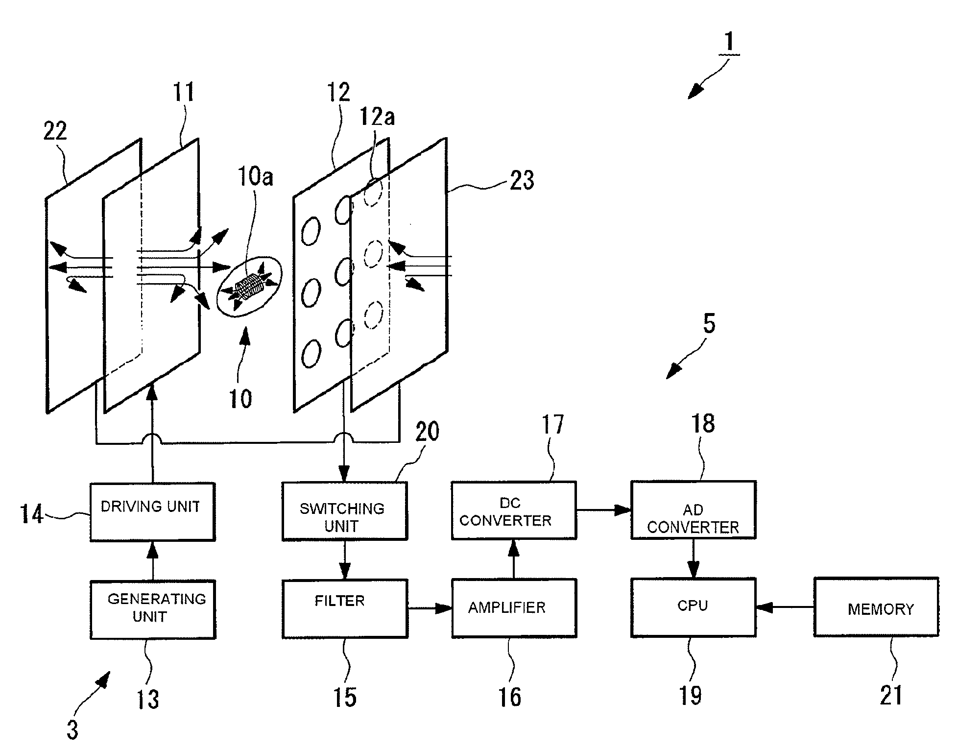
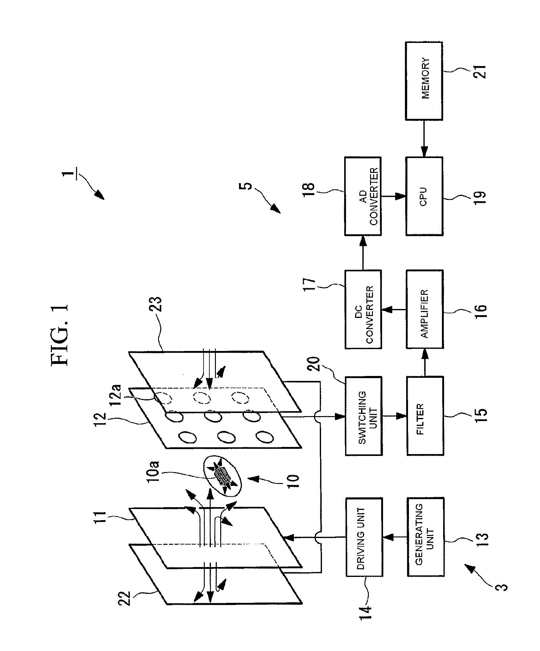
[0053]FIG. 1 is a schematic view illustrating the outline of a position detection apparatus according to the first embodiment.

[0054]As shown in FIG. 1, a position detection apparatus 1 is mainly formed of a magnetic-field generating coil (first magnetic-field generating unit) 11 that generates an alternating magnetic field (first magnetic field); a magnetic-field sensor (magnetic-field detecting unit) 12 that detects an induced magnetic field generated by an embedded coil 10a installed on an object 10 to be detected; a driving unit 3 that is used for driving control of the magnetic-field generating coil 11; a detecting unit (magnetic-field detecting unit) 5 that processes a signal output from the magnetic-field sensor 12; a reversed-phase-magnetic-field generating coil (second magnetic-field generating unit, second magnetic-field genera...

second embodiment

[0098]A position detection apparatus according to a second embodiment of the present invention will be described below with reference to FIG. 5.

[0099]The basic configuration of the position detection apparatus according to this embodiment is the same as that in the first embodiment; however, the structures of the reversed-phase-magnetic-field generating coil and the periphery thereof are different from those in the first embodiment. Thus, in this embodiment, only the structures of the reversed-phase-magnetic-field generating coil and the periphery thereof shall be described with reference to FIG. 5, and the description of the structures of other components shall be omitted.

[0100]FIG. 5 is a schematic view illustrating the outline of the position detection apparatus according to this embodiment.

[0101]The same components as those in the first embodiment are denoted with the same reference numerals, and thus will not be described.

[0102]As shown in FIG. 5, a position detection apparatus...

third embodiment

[0116]A position detection apparatus according to a third embodiment of the present invention will be described below with reference to FIG. 6.

[0117]The basic configuration of the position detection apparatus according to this embodiment is the same as that in the second embodiment; however, the structures of the reversed-phase-magnetic-field generating coil and the periphery thereof are different from those in the second embodiment. Thus, in this embodiment, only the structures of the reversed-phase-magnetic-field generating coil and the periphery thereof shall be described with reference to FIG. 6, and the description of the structures of other components shall be omitted.

[0118]FIG. 6 is a schematic view illustrating the outline of the position detection apparatus according to this embodiment.

[0119]The same components as those in the second embodiment are denoted with the same reference numerals, and thus will not be described.

[0120]As shown in FIG. 6, a position detection apparat...


PUM


Abstract

A position detection apparatus and a medical-device-position detection system that have improved position detection accuracy are provided by setting high amplification for the position detection apparatus. The position detection apparatus includes a circuit that has at least one embedded coil (10a) and that is provided inside an object (10) to be detected; a first magnetic-field generating unit (11) for generating a first magnetic field in the region where the embedded coil (10a) is disposed; a magnetic-field detecting unit (5, 12) for detecting an induced magnetic field generated at the embedded coil (10a) by the first magnetic field; and a second magnetic-field generating unit (23) for generating a second magnetic field having a phase substantially opposite to the phase of the first magnetic field.

Description

CROSS REFERENCE TO RELATED APPLICATION[0001]The present application is a 35 U.S.C. §§371 national phase conversion of PCT / JP2006 / 316082 filed 16 Aug. 2006, which claims priority from Japanese patent application 2005-242359 filed 24 Aug. 2005, which is herein incorporated by reference. The PCT International Application was published in the Japanese language.BACKGROUND OF THE INVENTION[0002]1. Field of the Invention[0003]The present invention relates to a position detection apparatus and a medial-apparatus-position detection system.[0004]2. Description of Related Art[0005]Recently, there has been research and development of swallowable capsule medical devices (objects to be detected), as represented by capsule endoscopes and the like, that are swallowed by a subject to enter the subject's body, where they traverse a passage in the body cavity to capture images of a target site inside the passage in the body cavity.[0006]To guide such a capsule medical device to a predetermined positio...

Claims


Application Information

Patent Timeline
Patent Type & Authority Patents(United States)
IPC IPC(8): A61B5/05
CPCA61B1/00158A61B5/062G01V3/105A61B1/041
Inventor KIMURA, ATSUSHIUCHIYAMA, AKIOSATO, RYOJI
Owner OLYMPUS CORP
Why Eureka
Try Eureka