Top opening, modular top rail, multi-rifle adaptable free float rail adaptor system (ARM-R)

a free floating rail adaptor and modular top rail technology, applied in the field of firearm accessories and mounting devices, can solve the problems of inability of users to mount accessories which would traditionally be attached to rail interface systems, deficiency of gas piston systems in several areas, and inability to achieve the effect of minimizing heat transfer and well ventilated

Active Publication Date: 2012-03-27
LWRC INTERNATIONAL
View PDF13 Cites 88 Cited by
  • Summary
  • Abstract
  • Description
  • Claims
  • Application Information

AI Technical Summary

Problems solved by technology

The disadvantage of this is dirty gases and carbon residues are deposited into the rifle's action and with sustained fire can lead to eventual failure as the close tolerance parts are caked with carbon.
Unfortunately the new system left the traditional M16 / M4 rifle equipped with a gas piston system deficient in several areas in which it previously was proficient.
Free float tubes and rails are necessary to prevent pressure from bi-pods and other accessories from pushing the hand guard, tube or rail into contact with the barrel thus compromising the weapon's accuracy potential.2. Also recognized is the inability of the user to mount accessories which would traditionally be attached to rail interface systems.
Currently available rails do not interface with a gas system and / or do not allow for access to the operating system for maintenance.3. Other rails currently available do not facilitate the user's access to the gas piston operating system for cleaning without the total removal of the free float device.
Removal of the free floating rail in its entirety to clean the operating system of the weapon will result in a loss of zero, or the ability of the weapon to direct a discharged bullet to a desired location would be compromised.
In effect a military user would be prohibited from cleaning his / her weapon while in a combat environment.4. Many currently available rail adaptor systems are difficult to install requiring an armorer or gunsmith with special tools to do the work.
None have provisions to allow easy access to parts underneath the top rail of the hand guard, leaving the user to abandon maintenance of the parts once the RAS is installed.
No prior art documents describe or illustrate a RAS which is readily adaptable to either a gas piston or direct gas impingement rifle design.
There is no evidence of an RAS being conceived that could switch between rifles of one family to another with the use of simple conversion parts.
No currently available RAS may be installed without a series of specialized tools.
A standard free float RAS cannot be used because gas piston systems require the user to remove, clean and maintain the parts of the gas system.
All prior RAS designs were closed tubes or semi-permanent installations, not allowing clearance or access to the gas system.
No other design is known which offers the above mentioned capabilities on a gas piston operated firearm.
No other publicly known design offers this modularity between both gas piston operated rifles and direct gas impingement operated rifles.
None of these tasks can be performed without specific tools or a shop available to the end users.
Yet these RAS's do not readily allow access to the parts enclosed by the RAS, making them unsuitable for gas piston designs.
If not installed correctly by a competent armorer or gunsmith, the removal of the barrel assembly and other parts listed previously to install a conventional RAS can lead to disaster.
Problems can include the gas tube being bent, barrel being bent, cross threading of the barrel nut during installation, or over-torque of the barrel nut.
No other publicly known design offers ease of installation with the practical advantages this system offers.
No other publicly known or known patented system offers the ease or flexibility and cost effective manufacture with all mentioned practical advantages.
Examples such as the Lewis Machine and Tool “Monolithic Rail Platform” and the Troy Industries MRF-C do offer a continuous top Mil. Std. 1913 rail, but neither offers the ability to easily install and remove the 12 o'clock rail which allows access to the gas system parts or allows easy installation and removal of the RAS by the end users.
No RAS found or related prior art allows the proper clearance for the gas piston system to protect it, ventilate it, and allow for convection cooling of the barrel assembly and gas system.
This will negatively affect calibrated optics such as the Trijicon ACOG, well known in the prior art, and very common in military, law enforcement and civilian circles.

Method used


Image

  • Top opening, modular top rail, multi-rifle adaptable free float rail adaptor system (ARM-R)
  • Top opening, modular top rail, multi-rifle adaptable free float rail adaptor system (ARM-R)
  • Top opening, modular top rail, multi-rifle adaptable free float rail adaptor system (ARM-R)

Examples


Embodiment Construction

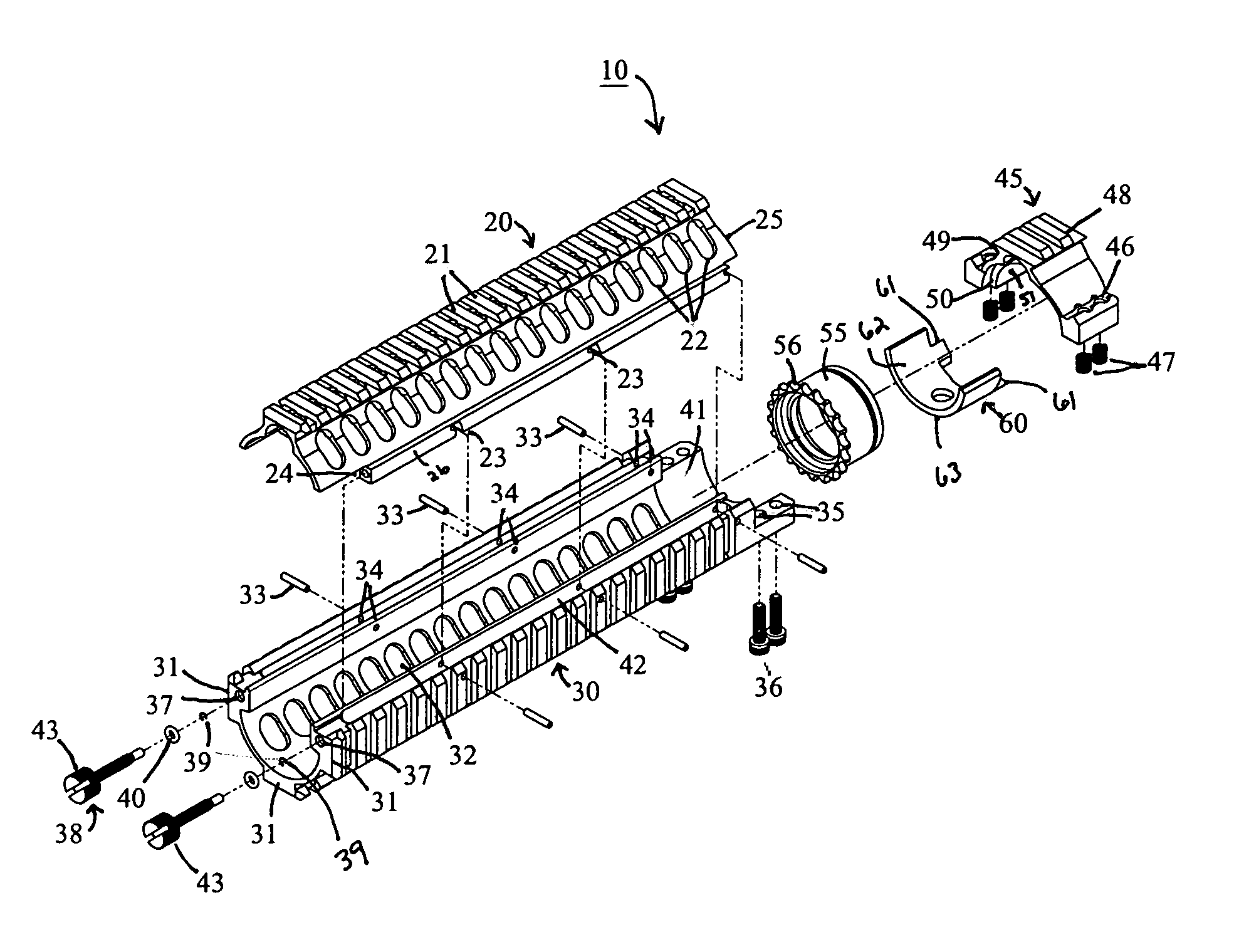
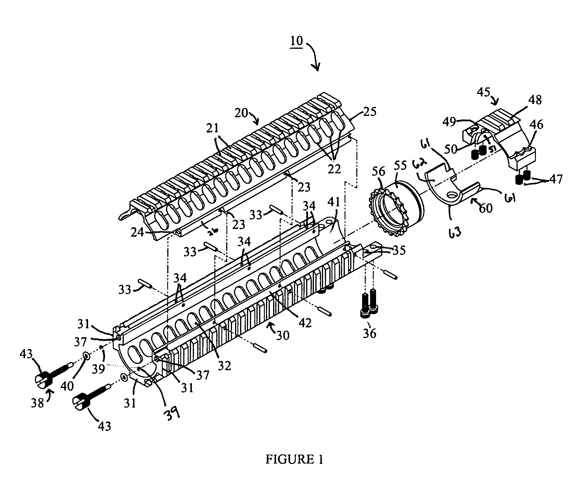
[0057]Turning now to the drawings in which like reference characters indicate corresponding elements throughout the several views, attention is directed to FIG. 1. The Top opening, Modular Top Rail, Multi-Rifle adaptable Free Float Rail accessory system generally designated by reference numeral 10, hereinafter referred to as “RAS”, has five main components which are shown in FIG. 1. The five primary components of the herein described RAS 10 are the top portion generally designated by reference numeral 20, the bottom portion generally designated by reference numeral 30, the clamp assembly generally designated by reference numeral 45, the barrel nut 55 and the anti-rotational device, generally designated by reference numeral 60.

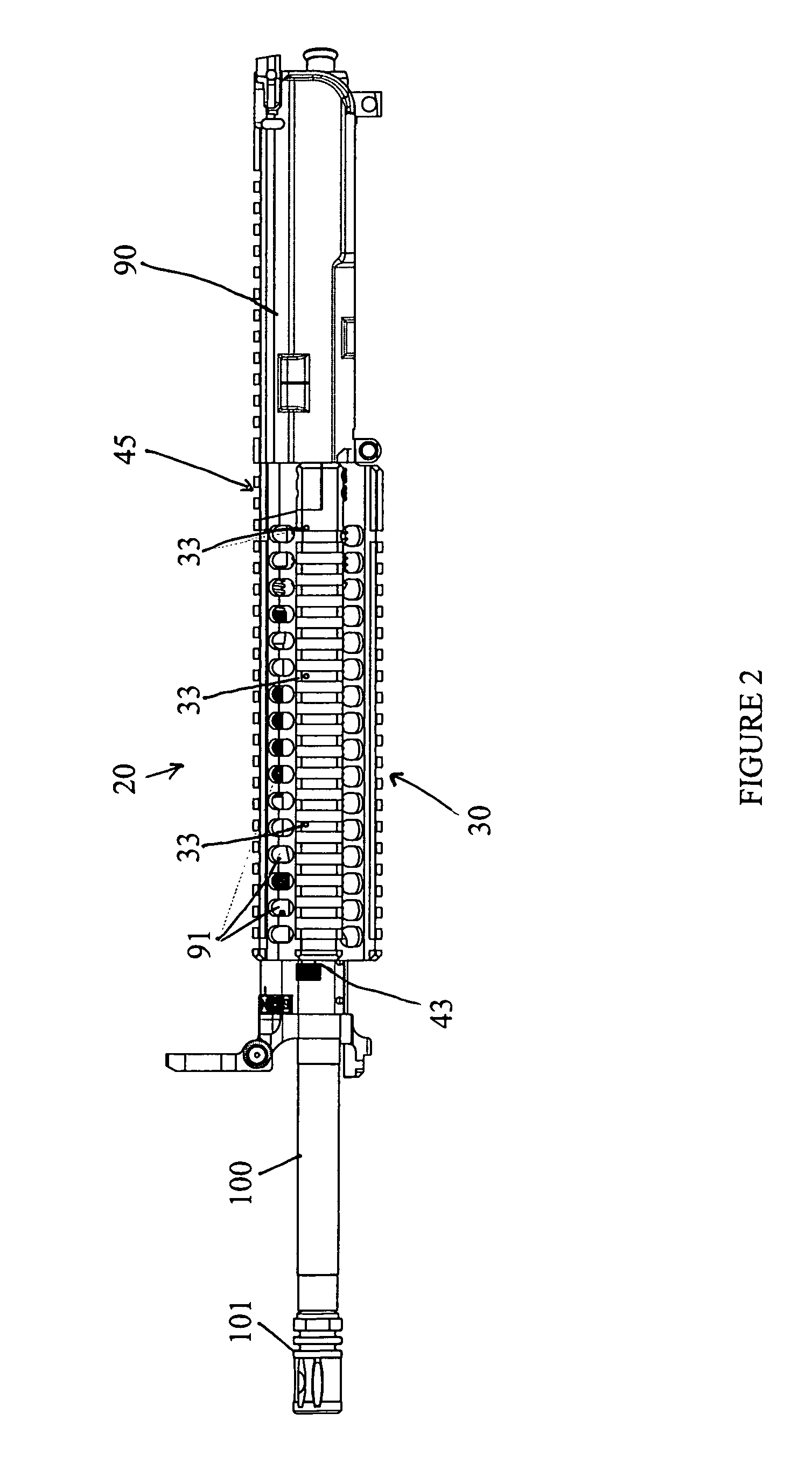
[0058]For purposes of this description, the term forward is intended to refer to the direction toward the muzzle 101 of barrel 100, and rearward is directed toward the receiver 90. The bore of the barrel 100, common throughout the prior art, constitutes the bor...


PUM


Abstract

An improved Rail Adaptor System / Rail Accessory System (RAS) which attaches to a firearm. The rail is top opening, modular, and free floats the barrel. Provided is a rigid, lightweight, strong platform for mounting firearm accessories. Heat transmission from the barrel assembly to the user is limited. The user is also protected from ventilated gases originating from the operating system. A quick detachable top rail section is provided so that that gas system may be easily accessed. This removable top section of the rail is what makes this device unique because the RAS may be installed without removing the barrel, gas system, front sight base, flash hider or the barrel nut. The herein described RAS is adaptable to a wide variety of firearms with the use of conversion parts. The top rail “returns to zero” on reinstallation allowing the remounting of various optics and electronic gun sites without the need to realign them.

Description

BACKGROUND OF THE INVENTION[0001]1. Field of Invention[0002]This invention relates to the field of firearms, specifically accessories and mounting devices for firearms.[0003]2. Prior Art[0004]Several years ago the military started the SCAR program to select a weapon which would replace all rifles currently utilizing a direct impingement operating system in use by the military. In short, a replacement of the M16 / M4 rifle was being sought.[0005]To explain the difference in the two systems, both direct gas impingement rifles and piston driven rifles have a hole toward the front end of the barrel. As the cartridge is fired, burning propellant causes the bullet to move down the bore of the rifle. The propellant burns, generating expanding gases thereby increasing the pressure behind the bullet. As the bullet passes the hole in the barrel, some of the gas is tapped off. This is where the direct gas impingement and piston driven rifles become different.[0006]In a direct impingement rifle t...

Claims


Application Information

Patent Timeline
Patent Type & Authority Patents(United States)
IPC IPC(8): F41G1/16
CPCF41C23/16
Inventor GOMEZ, JESUS S.MELLORS, DARREN
Owner LWRC INTERNATIONAL
Why Eureka
Try Eureka