Yarn color placement system

a color placement and yarn technology, applied in the field of yarn color placement system, can solve the problems of restricted production rate of such machines, limited application of specialized color patterning machines, etc., and achieve the effect of increasing or denser effective process stitch rate and enhancing density

Active Publication Date: 2012-03-27
CARD MONROE
View PDF150 Cites 50 Cited by
  • Summary
  • Abstract
  • Description
  • Claims
  • Application Information

AI Technical Summary

Benefits of technology

[0010]The yarn color placement system according to the principles of the present invention further generally will be operated at increased or denser effective process stitch rates than conventional tufting processes. Typically, the operative or effective stitch rate run by the yarn placement system will be approximately equivalent to a desired or prescribed fabric stitch rate or number of stitches per inch for the patterned tufted article being formed that is based upon the rate at which the backing material is fed and the gauge of the tufting machine, multiplied by the number of colors being run in the programmed pattern. As a consequence, as the needle bar(s) is shifted during the formation of the pattern stitches, for each color to be taken out or back-robbed and thus hidden in the finished patterned article, the increased number of stitches per inch will provide sufficient enhanced density between the high and low tufts of the finished patterned tufted article to avoid a missing color or gap being shown or otherwise appearing in the patterned tufted article.

Problems solved by technology

A problem exists, however, with such specialty tufting machines for individually placing yarns, in that the production rates of such machines generally are restricted as the yarns are placed individually in the backing material by the single needle or as the backing feed direction is changed.
As a consequence, such specialized color patterning machines typically are limited to special applications such as formation of patterned rugs or carpets of limited or reduced sizes.

Method used


Image

  • Yarn color placement system
  • Yarn color placement system
  • Yarn color placement system

Examples


Embodiment Construction

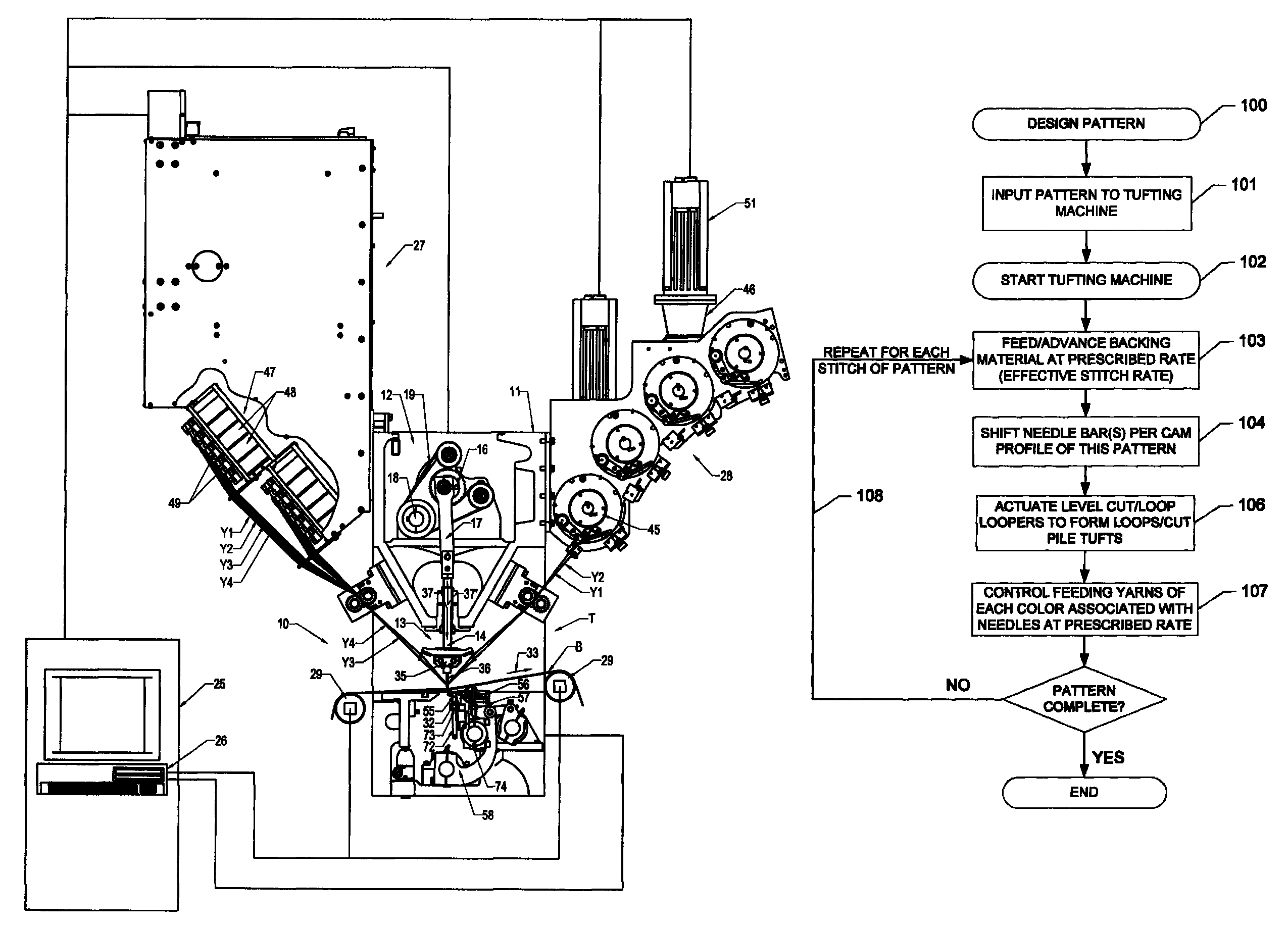
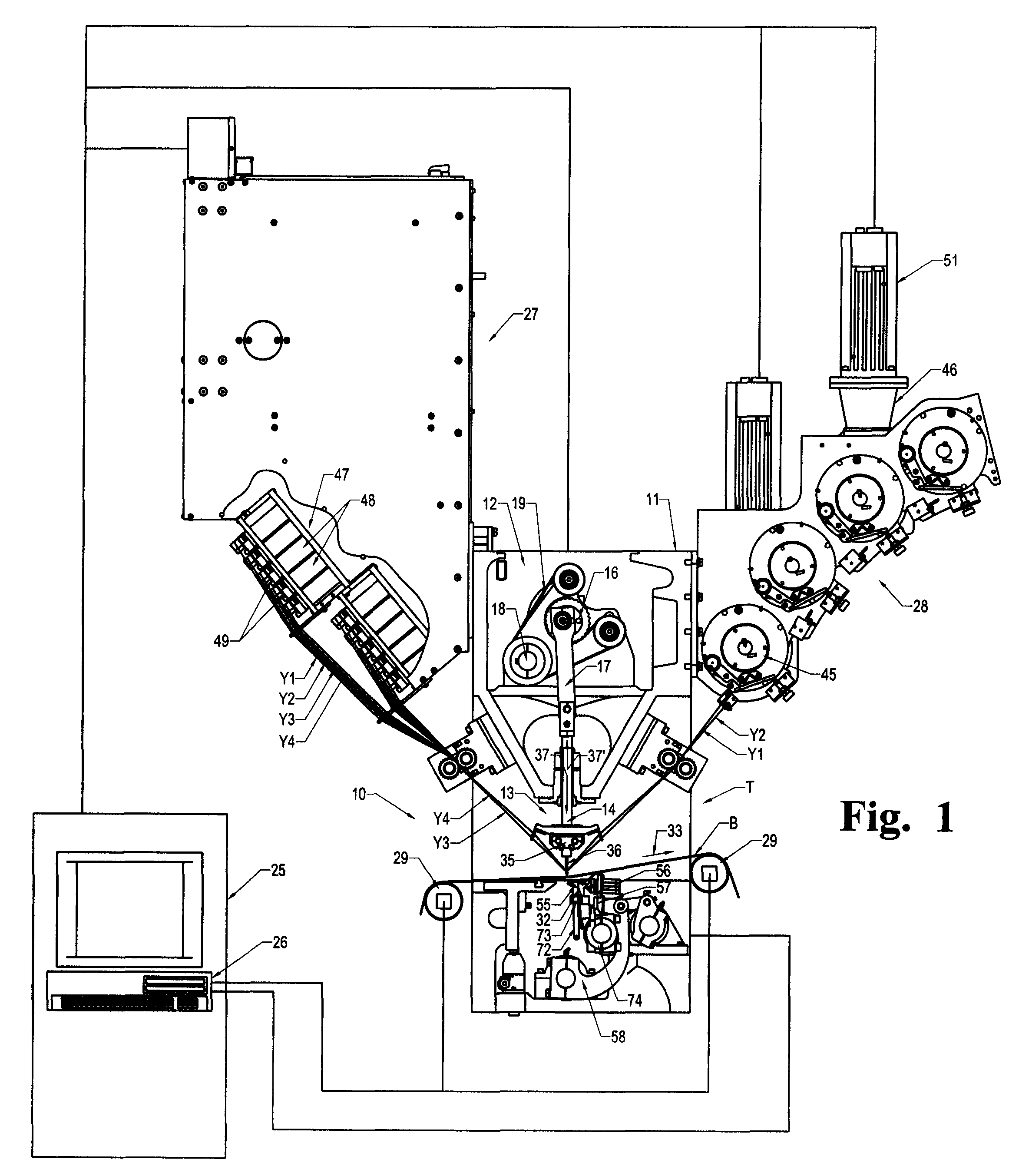
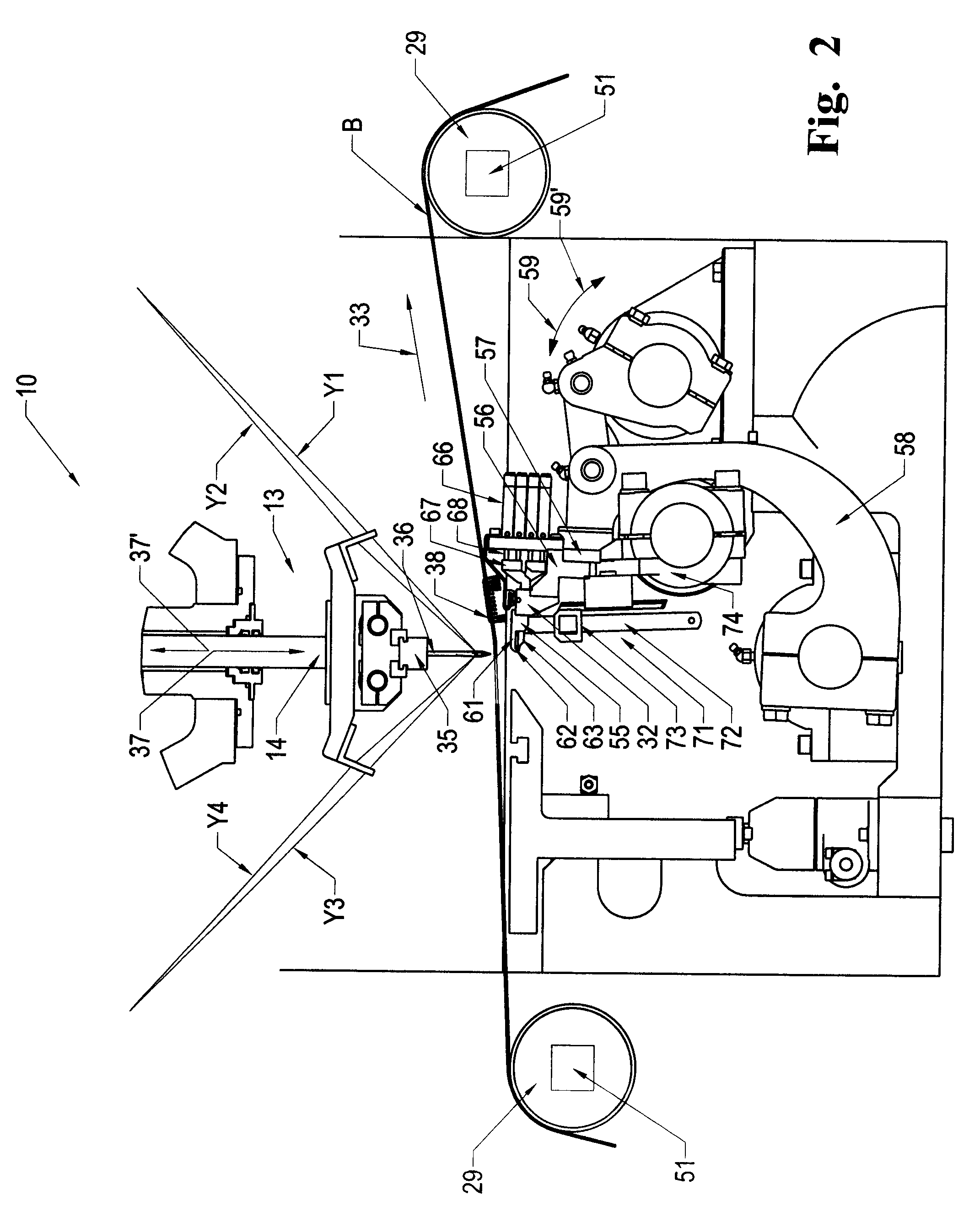
[0019]Referring now to the drawings in which like numerals indicate like parts throughout the several views, in accordance with one example embodiment of the yarn color placement system of the present invention, as generally illustrated in FIGS. 1-5, a tufting machine 10 is provided for controlling placement of yarns Y1-Y4, etc., of different colors at desired locations in a backing material B to form a tufted article having a variety of varying or free-flowing colored pattern effects therein. While four yarns / colors are indicated, it will be understood that more or fewer different color yarns (i.e., two color, three color, five color, six colors, etc., as illustrated in FIGS. 6A-6D) also can be utilized in the yarn color placement system of the present invention.

[0020]As generally illustrated in FIG. 1, the tufting machine 10 generally includes a frame 11, including a head portion 12 housing a needle bar drive mechanism 13 and defining a tufting zone T. The needle bar drive mechani...


PUM


Abstract

A yarn color placement system for a tufting machine including a series of different color yarns being fed to the needles of the tufting machine by yarn feed mechanisms. A backing material is fed through the tufting machine at an increased stitch rate as the needles are shifted according to the programmed pattern steps. A series of level cut loop loopers or hooks engage and pick loops of yarns from the needles, with the clips of the level cut loop loopers or hooks being selectively actuated to form cut pile tufts, while the remaining loops of yarns can be back-robbed so as to be hidden from view in the finished patterned tufted article.

Description

RELATED APPLICATION[0001]This application claims the benefit of U.S. Provisional Application No. 61 / 029,105, filed Feb. 15, 2008, which is hereby incorporated by reference in its entirety.FIELD OF THE INVENTION[0002]The present invention generally relates to tufting machines, and in particular, to a system for controlling the feeding and placement of yarns of different colors within a backing material passing through a tufting machine to enable formation of free-flowing patterns within a tufted article.BACKGROUND OF THE INVENTION[0003]In the tufting of carpets and other, similar articles, there is considerable emphasis placed upon development of new, more eye-catching patterns in order to try to keep up with changing consumer tastes and increased competition in the marketplace. In particular, there has been emphasis over the years on the formation of carpets that replicate the look and feel of fabrics formed on a loom. With the introduction of computer controls for tufting machines ...

Claims


Application Information

Patent Timeline
Patent Type & Authority Patents(United States)
IPC IPC(8): D05C15/30
CPCD05C15/26D05C15/30D05C15/36D05C15/34D05C15/32
Inventor HALL, WILTONJOHNSTON, KENDALL
Owner CARD MONROE
Why Eureka
Try Eureka