Device for preventing slipping of vehicle

a technology for preventing slipping and vehicles, applied in non-skid devices, vehicle components, wheels, etc., can solve the problems of affecting the safety of drivers, and the entire fixing force of vehicle slipping prevention devices is lost, so as to prevent the loosening of the engaging member, prevent the abrasion of spikes, and prevent the effect of disengagemen

Inactive Publication Date: 2012-03-27
PARK IL JUN
View PDF16 Cites 10 Cited by
  • Summary
  • Abstract
  • Description
  • Claims
  • Application Information

AI Technical Summary

Benefits of technology

[0048]As described above, the vehicle slipping prevention device according to the present invention has the following advantages.
[0049]1) It is possible to prevent an abrasion of spikes by riveting a rod made of tungsten or titanium in the spikes.
[0050]2) The structure of an engaging member able to engage a plurality of spikes connected with a connection member is changed to the structure having a locking member which is able to prevent disengagement. So, it is possible to prevent the loosening of an engaging member irrespective of the vibrations occurring as the vehicle runs.
[0051]3) The structure of an engaging member able to engage a plurality of spikes connected with a connection member is changed to a structure having a stripe shaped belt and tilting member, so that an easier engaging and disengaging work is implemented. Even a lot of vibrations occurring as the vehicle runs do not affect loosening. It is possible to maintain a tightened tensional force with respect to a plurality of spikes.
[0052]4) The spikes are closely contacted with the double wheels so that the connection member can be bent and separated, so that a position change and vibrations owing to the rotation of double wheels do not occur. The noises are reduced. Only the part, which needs a change or maintenance, can be removed, so that the cost needed for part change and maintenance can be significantly saved.
[0053]5) The auxiliary chain and subsidence prevention piece are provided in the spikes, so that when a vehicle runs on a road having a lot of subsidence, a slipping and subsidence are prevented, and a driving force is enhanced.

Problems solved by technology

In the integral type vehicle slipping prevention device, when a connection ring or a connection cable is broken and disconnected, the entire fixing force of a vehicle slipping prevention device is lost, and the entire structure of a vehicle slipping prevention device may be separated from the tire.
Even when not separated, it is impossible to recycle the same.
In the integral type vehicle slipping prevention device, a woman driver or a weak or disabled driver is not able to easily engage or disengage the device.
When a driver meets a sudden snow or icy road, it is impossible to fast engage the device.
Since it is needed to engage or disengage the device while moving the vehicle forward or backward, it is impossible to engage or disengage the device on a slanted road.
So, the integral type vehicle slipping prevention device has a problem for engaging to a large size vehicle which is equipped with double wheels.
In the integral type vehicle slipping prevention device, it is difficult to engage and disengage the chain.
In consideration with a narrow width and small diameter of a double-wheel tire used in a freight transportation vehicle, the vehicle slipping prevention device designed for a passenger car may have a smaller fixing force or a smaller close-contacting force when it is engaged to the tires of a truck or a bus, so that it is impossible to provide an efficient driving force transfer and stop force.
In this case, when the total weight is focused on the snow chain, the chains may be damaged or disengaged.
In the conventional vehicle slipping prevention device, when a vehicle runs, the weights are focused on the device, and the engaged portions of the fixed snow chains may be disengaged, so that the braking force sharply loses, and a large accident may occur.
Namely, the stability of the conventional device is largely decreased.
When a vehicle runs on a non-uniform ground, the snow chains may be gathered at one side and may be tangled, so that the braking force may be applied in a centrifugal force direction owing to the sudden cornering operation or the vehicle is steered in a certain direction opposite to the direction that the driver steers, so an accident may occur.
In addition, when a vehicle runs a long distance or runs on a snow road or a unpaved road, a lot of abrasion may occur in the surfaces of the spikes.

Method used


Image

  • Device for preventing slipping of vehicle
  • Device for preventing slipping of vehicle
  • Device for preventing slipping of vehicle

Examples


first embodiment

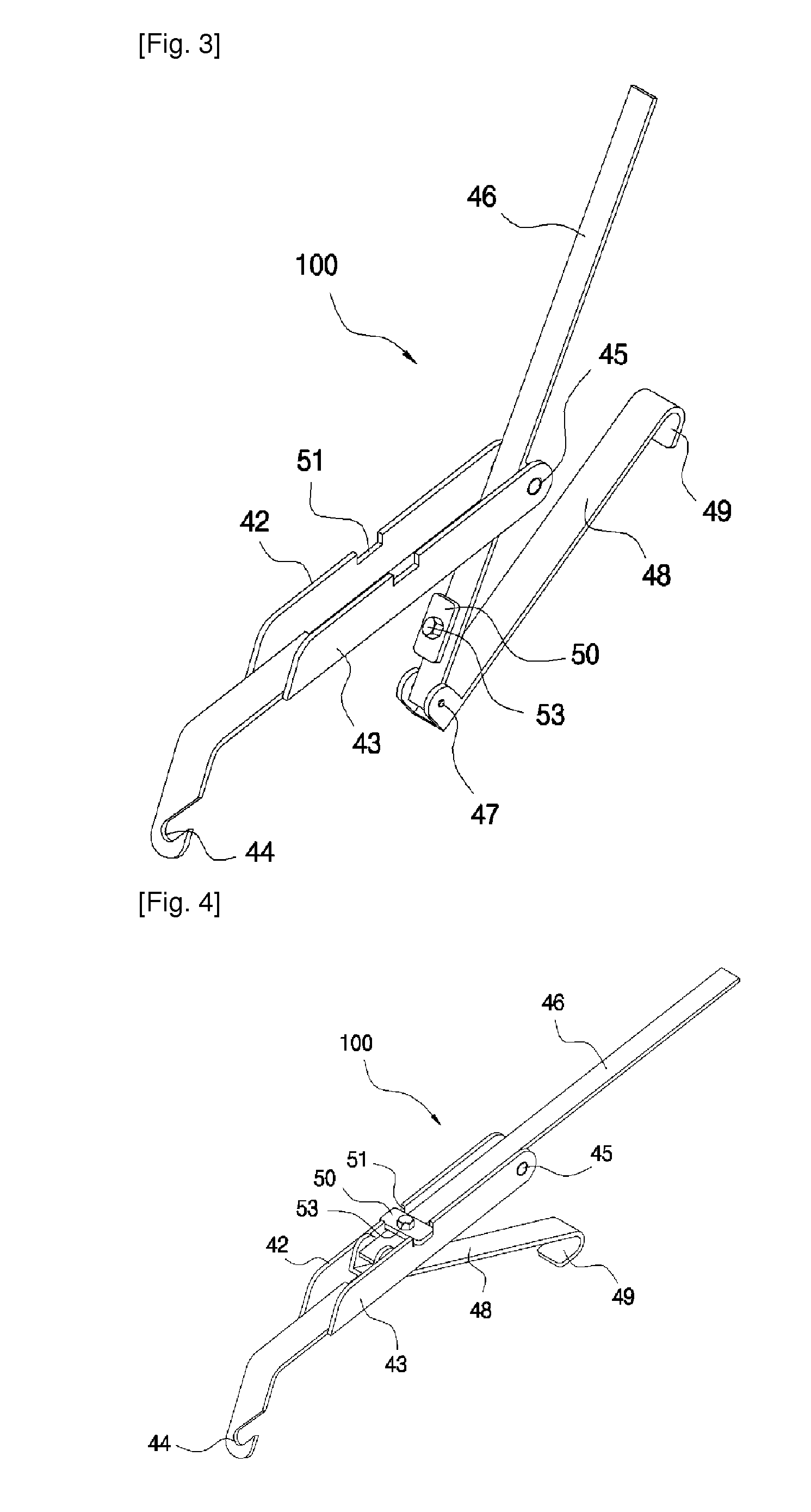
[0093]The construction of the engaging member and their engaging method according to the present invention will be described.

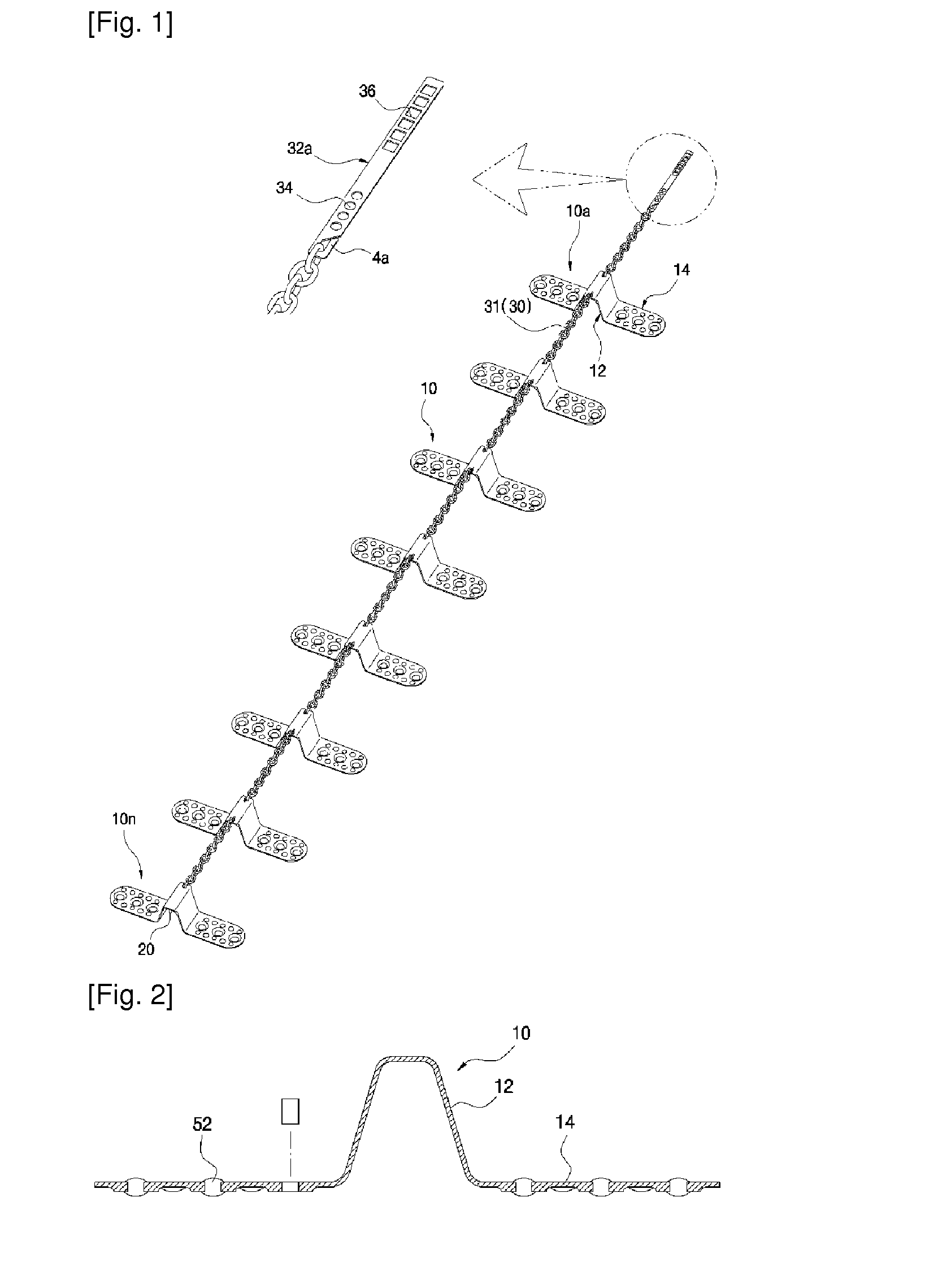
[0094]FIGS. 3 and 4 are perspective views illustrating a first engaging member of a vehicle slipping prevention device according to the present invention, and FIG. 5 is a perspective view illustrating a use state of a first engaging member of a vehicle slipping prevention device according to the present invention.

[0095]The first engaging member 100 comprises a pair of first and second support plates 42 and 43 arranged in parallel at both sides of a longitudinal rectangular plate, a hook 44 which is integrally formed at each end of the first and second support plates 42 and 43 and is hooked at the chain 31 of the connection member 30, a longitudinal tightening member 46 which is disposed between the space of the other ends of the first and second support plates 42 and 43 with its intermediate portion being engaged by a hinge 45, and an integrally bent tensional...

second embodiment

[0102]The engaging member and its engaging method according to the present invention will be described.

[0103]FIGS. 8 and 9 are perspective views illustrating a second engaging member and its use state of a vehicle slipping prevention device according to the present invention.

[0104]The second engaging member 200 according to the second embodiment of the present invention is similar with the first engaging member 100 of the first embodiment except that the separable hook 55 and the separable engaging ring 56 are inserted into the belt 54 in a separable structure.

[0105]The second engaging member 200 comprises a pair of longitudinal first and second support plates 42 and 43 like the first engaging member 100, a tightening member 46 which is disposed in the space between the ends of the first and second support plates 42 and 43 with its intermediate portion being engaged by a hinge 45, and a tensional force maintaining member 48 of which one end is engaged to the inner end of the tighten...

third embodiment

[0111]The engaging member and its engaging method according to the present invention will be described.

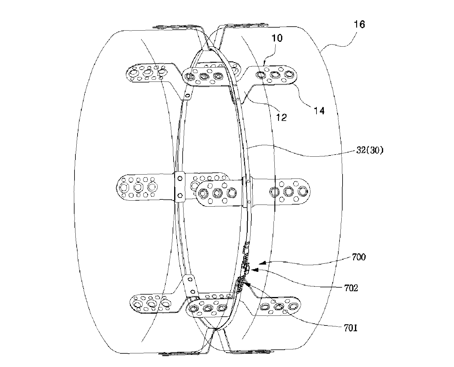
[0112]FIGS. 10 and 11 are perspective views illustrating a third engaging member of a vehicle slipping prevention device according to the present invention. FIG. 14 is a perspective view illustrating a use state of a third engaging member of a vehicle slipping prevention device according to the present invention. FIGS. 15 and 16 are perspective views illustrating a construction that a vehicle slipping prevention device is installed in a double wheel tire by using a third engaging member according to the present invention.

[0113]The third engaging member 300 according to the third embodiment of the present invention is implemented by using a belt and a tilting plate.

[0114]Here, the belt 54 has a certain length. As shown in FIG. 13, a metallic protection cap 59 may be provided at both ends of the belt 54 for preventing abrasion. A coating layer 60 coated with a heterogeneous material ...


PUM


Abstract

A device for preventing slipping of a vehicle is disclosed, which improves a vehicle slipping prevention device in which a plurality of spikes connected with a connection member are inserted into a gap between double wheels disposed at a rear side of a large size vehicle at regular intervals for preventing slipping. In the present invention, a structure contacting with a tire surface along with a spike is newly improved, and a structure of an engaging member used for maintaining the tensional force of a plurality of spikes connected by means of a connection member is newly improved. It is possible to achieve a fast and simple engaging and disengaging work and to keep a substantial tensional force so that a vehicle slipping prevention device is not disengaged even during a long time drive of a vehicle.

Description

[0001]This application is the U.S. national phase of International Application No. PCT / KR2008 / 001270 filed 6 Mar. 2008, which designated the U.S. and claims priority to KR Application No. 10-2007-0023109 filed 8 Mar. 2007, the entire contents of each of which are hereby incorporated by reference.TECHNICAL FIELD[0002]The present invention relates to a device for preventing slipping of a vehicle, and in particular to a device for preventing slipping of a vehicle which improves a vehicle slipping prevention device in which a plurality of spikes connected with a connection member are inserted into a gap between double wheels disposed at a rear side of a large size vehicle at regular intervals for preventing slipping. In the present invention, a structure contacting with a tire surface along with a spike is newly improved, and a structure of an engaging member used for maintaining the tensional force of a plurality of spikes connected by means of a connection member is newly improved. It...

Claims


Application Information

Patent Timeline
Patent Type & Authority Patents(United States)
IPC IPC(8): B60C27/06
CPCB60C27/22
Inventor PARK, IL-JUN
Owner PARK IL JUN
Why Eureka
Try Eureka