Controlling torque in a flywheel powertrain

a technology of control torque and flywheel, applied in the field of powertrain, can solve the problems of large control perturbations, difficult measurement of wheel slip in a vehicle, and measurement difficulty, and achieve the effect of reducing slip error

Inactive Publication Date: 2012-03-27
FORD GLOBAL TECH LLC
View PDF28 Cites 14 Cited by
  • Summary
  • Abstract
  • Description
  • Claims
  • Application Information

AI Technical Summary

Benefits of technology

[0006]A method for controlling a powertrain for a motor vehicle includes determining a desired flywheel torque, determining, with reference to the desired flywheel torque, a desired torque capacity torque of a clutch through which torque is transmitted between the flywheel and wheels of the vehicle, operating the clutch to produce the desired clutch torque capacity, determining a slip error across the clutch, and changing a gear ratio of a continuously variable transmission located in a drive path between the clutch and said wheels to a gear ratio that reduces the slip error.
[0010]The method employs easy to measure input speed signals rather than wheel slip signals. Open loop control of the flywheel output torque reduces fluctuation of torque at the wheels. Closed loop control of clutch slip causes only minor perturbations to the output torque.

Problems solved by technology

A major challenge present by flywheel systems is the need to provide robustly and smoothly the flywheel torque to the wheels.
This measurement can be difficult since it is very stiff and can change with environmental conditions, creating the need to have very accurate ratio control.
Wheel slip is a difficult measurement to make in a vehicle particularly under low loads, and it has a high gain.
Small errors in this measurement can cause large control perturbations.

Method used


Image

  • Controlling torque in a flywheel powertrain
  • Controlling torque in a flywheel powertrain
  • Controlling torque in a flywheel powertrain

Examples


Embodiment Construction

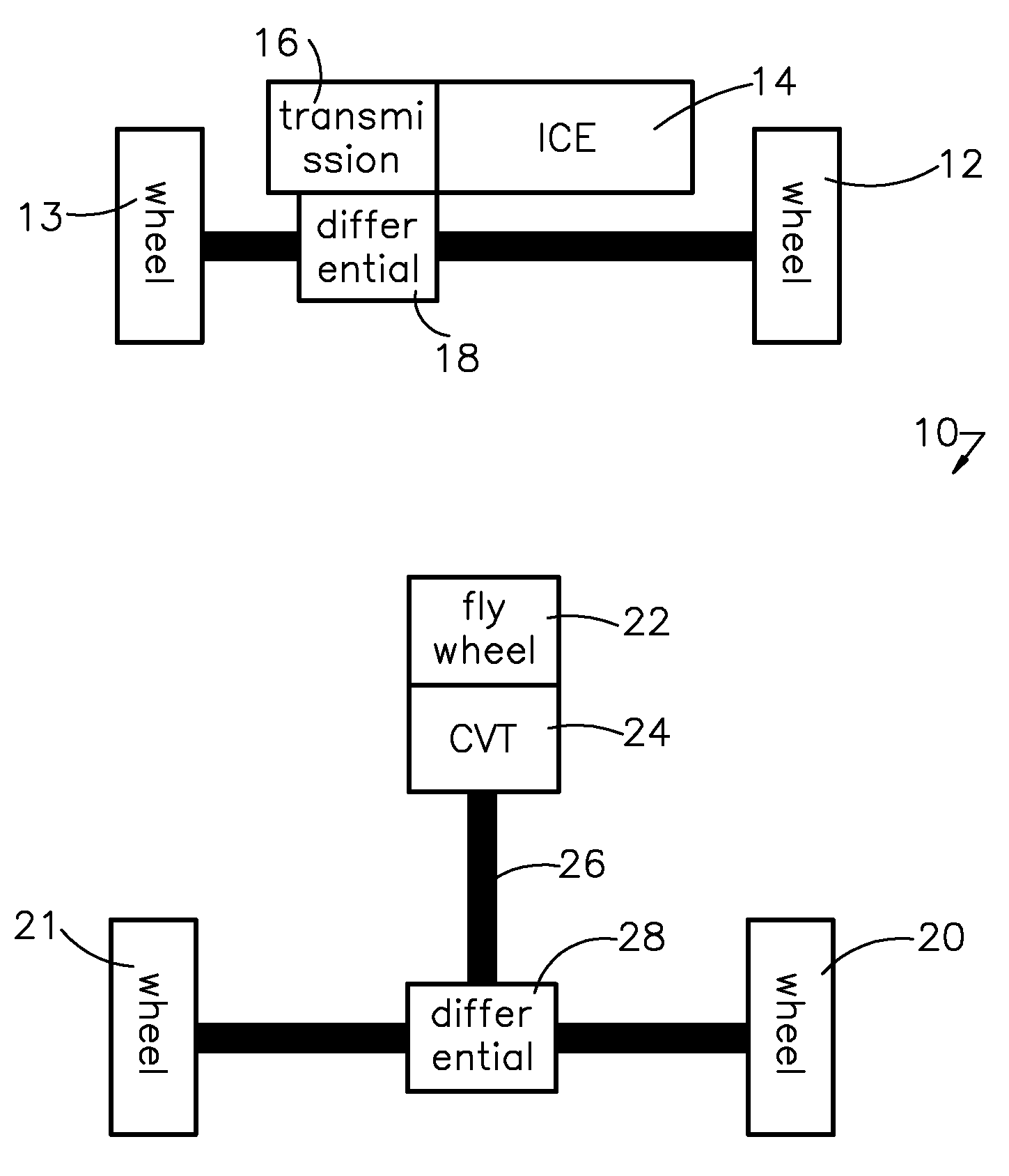
[0016]Referring now to the drawings, FIG. 1 illustrates schematically a hybrid powertrain 10 for a motor vehicle. The front wheels 12, 13 are driveable connected to a power source 14, such as an internal combustion engine (ICE) through a transmission 16, preferably a multiple-speed step change transmission, and a front differential mechanism 18. The rear wheels 20, 21 are driveable connected to a hybrid power source, such as a flywheel assembly 22, through a transmission 24, preferably a continuously variable transmission (CVT), driveshaft 26 and rear differential mechanism 28. The CVT 24, which produces a stepless, continuously variable ratio of the speed of its input to the speed of its output. Belt drive mechanisms and traction drive mechanisms are used to transmit power through the CVT 24.

[0017]In this hybrid powertrain 10, wheel braking energy is regenerated and stored mechanically in flywheel 22. The speed ratio of the CVT 24 is varied to allow rotating energy to be either sto...


PUM


Abstract

A method for controlling a powertrain for an automotive vehicle includes determining a desired flywheel torque, determining, with reference to the desired flywheel torque, a desired torque capacity torque of a clutch through which torque is transmitted between the flywheel and wheels of the vehicle, operating the clutch to produce the desired clutch torque capacity, determining a slip error across the clutch, and changing a gear ratio of a continuously variable transmission located in a drive path between the clutch and said wheels to a gear ratio that reduces the slip error.

Description

BACKGROUND OF THE INVENTION[0001]1. Field of the Invention[0002]This invention relates generally to a powertrain for a motor vehicle and, more particularly, to controlling torque transmitted between a flywheel and vehicle wheels.[0003]2. Description of the Prior Art[0004]A hybrid vehicle powertrain combines a conventional propulsion system, which includes an internal combustion engine and a step-change automatic transmission, with an energy storage system to improve fuel economy over a conventional vehicle powertrain. Various techniques for regenerating and storing kinetic energy of the vehicle include electric systems, which include an electric motor and electric storage battery; hydraulic systems, which store energy in a pressurized hydraulic tank and flywheel systems, which store energy in a rotating flywheel or disc.[0005]A major challenge present by flywheel systems is the need to provide robustly and smoothly the flywheel torque to the wheels. One way that has been proposed is...

Claims


Application Information

Patent Timeline
Patent Type & Authority Patents(United States)
IPC IPC(8): B60W10/00B60K25/10
CPCB60K6/105B60K6/365B60K6/442B60K6/52B60K6/543B60W10/107B60W10/02Y10T477/6203Y02T10/6204Y02T10/6234Y02T10/6265B60W2710/025Y02T10/62B60W2050/0012
Inventor ORTMANN, WALTER J.
Owner FORD GLOBAL TECH LLC
Why Eureka
Try Eureka