Heating resistor element, manufacturing method for the same, thermal head, and printer

a manufacturing method and resistor technology, applied in the field of heat dissipation resistor elements, can solve the problems of difficult to let out heat from the hollow portion to the insulating substrate side, and difficult to manufacture or handle thin plate glass having a thickness of 100 m, etc., to achieve easy manufacturing, promote more active heat dissipation, and facilitate formation

Inactive Publication Date: 2012-03-27
SEIKO INSTR INC
View PDF5 Cites 10 Cited by
  • Summary
  • Abstract
  • Description
  • Claims
  • Application Information

AI Technical Summary

Benefits of technology

[0009]The present invention has been made in view of the circumstances described above, and therefore an object thereof is to provide a heating resistor element capable of suppressing heat accumulation in the gas contained in the hollow portion and improving the printing quality, a manufacturing method for the same, a thermal head, and a printer.

Problems solved by technology

In this case, it is difficult to manufacture or handle the thin plate glass having a thickness of 100 μm or less, and thus thin plate glass having a thickness, which is relatively easily handled, is bonded to a surface of the silicon substrate, and then a surface of a side opposite to a bonded surface is chipped by etching or polishing to obtain a desired thickness size.
However, in the conventional heating resistor element, the hollow portion is formed by etching or laser processing, and hence a surface of the inner surface of the hollow portion on the insulating substrate side is formed to be extremely smooth, whereby there is an inconvenience that heat of the hollow portion is difficult to be transmitted to the insulating substrate side.
For this reason, the heat transmitted to the gas is difficult to be let out to the insulating substrate side, and is accumulated in the gas.
Therefore, if the printing is performed for a long period of time, the hollow portion becomes a heat source, which results in a problem of decreased printing quality, such as an occurrence of a tailing phenomenon in which printed characters are connected together in a sheet feeding direction.

Method used


Image

  • Heating resistor element, manufacturing method for the same, thermal head, and printer
  • Heating resistor element, manufacturing method for the same, thermal head, and printer
  • Heating resistor element, manufacturing method for the same, thermal head, and printer

Examples


Embodiment Construction

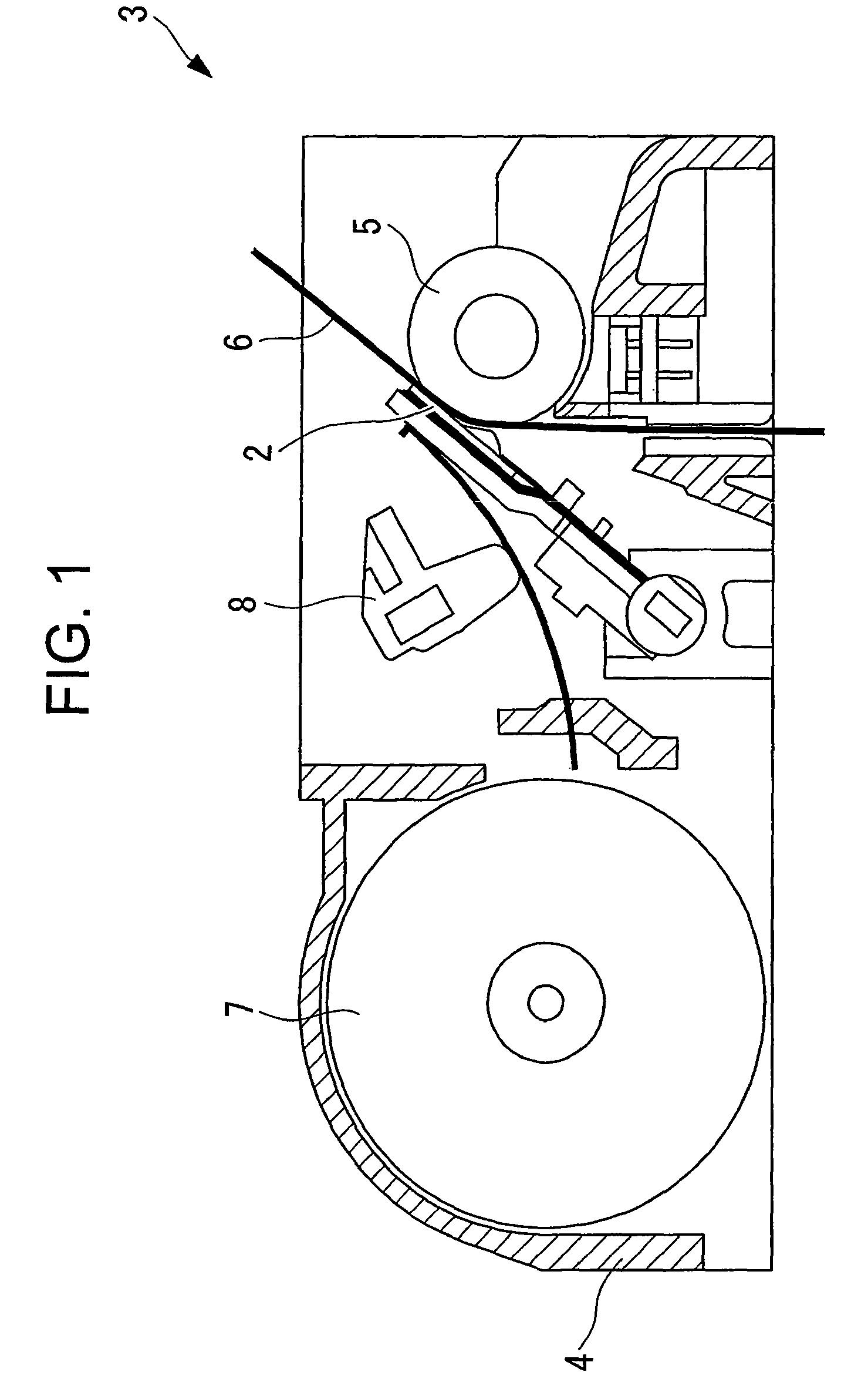
[0044]Hereinafter, a heating resistor element 1, a manufacturing method for the same, a thermal head 2, and a thermal printer (printer) 3 according to an embodiment of the present invention are described with reference to FIGS. 1 to 7.

[0045]The heating resistor element 1 according to this embodiment is used in the thermal head 2 of the thermal printer 3 shown in FIG. 1.

[0046]The thermal printer 3 includes a body frame 4, a platen roller 5 which is horizontally arranged, the thermal head 2 which is arranged to be opposed to an outer periphery of the platen roller 5, a sheet feeding mechanism 7 feeding thermal paper 6 between the platen roller 5 and the thermal head 2, and a pressurizing mechanism 8 pressing the thermal head 2 against the thermal paper 6 with a predetermined pressing force.

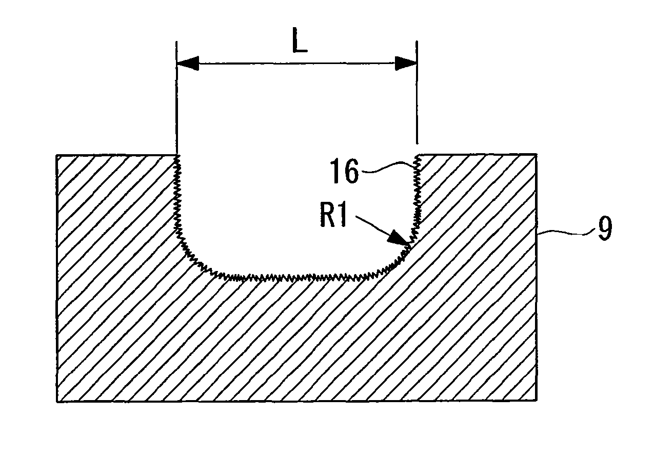
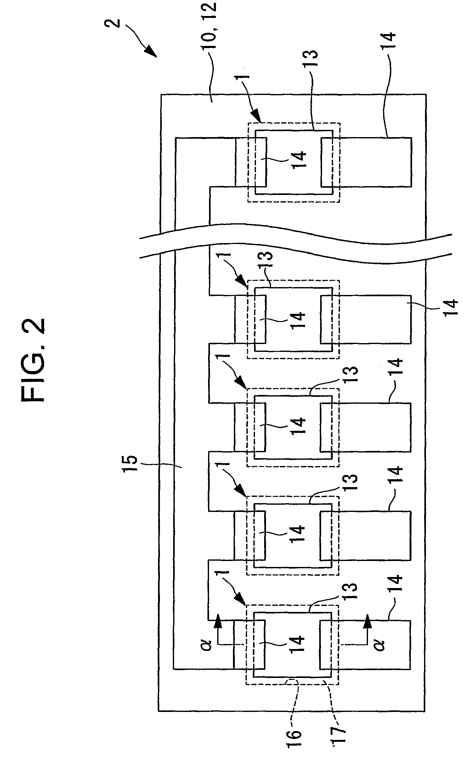
[0047]The thermal head 2 is formed in a flat plate-like shape as shown in a front view of FIG. 2, and includes a plurality of heating resistor elements 1 at intervals. As shown in a vertical cross s...


PUM

PropertyMeasurementUnit
surface roughness Raaaaaaaaaaa
depthaaaaaaaaaa
depthaaaaaaaaaa

Abstract

Provided is a heating resistor element (1), including: an insulating substrate (9); a heat accumulating layer (10) bonded to a surface of the insulating substrate (9); and a heating resistor (11) provided on the heat accumulating layer (10), in which: on at least one of bonded surfaces (9a) between the insulating substrate (9) and the heat accumulating layer (10), at least one of the insulating substrate (9) and the heat accumulating layer (10) is provided with a concave portion (16) in a region opposed to the heating resistor (11) to form a hollow portion (17); and the hollow portion (17) includes an inner surface on a side of the insulating substrate (9), the inner surface being processed to have surface roughness (Ra) of 0.2 μm or more. Accordingly, heat accumulation in a gas of the hollow portion (17) can be suppressed to improve printing quality.

Description

RELATED APPLICATIONS[0001]This application claims priority under 35 U.S.C. §119 to Japanese Patent Application Nos. JP2007-275570 filed on Oct. 23, 2007 and JP2008-218636 filed on Aug. 27, 2008, the entire contents of which are hereby incorporated by reference.BACKGROUND OF THE INVENTION[0002]1. Field of the Invention[0003]The present invention relates to a heating resistor element, a manufacturing method for the same, a thermal head, and a printer.[0004]2. Description of the Related Art[0005]Conventionally, in a heating resistor element provided in a thermal head of a printer, in order to improve heating efficiency of a heating resistor and to reduce power consumption, a hollow portion is formed in a region opposed to the heating resistor, and the hollow portion is caused to function as a heat insulating layer having low heat conductivity, thereby controlling an amount of heat flowing from the heating resistor to an insulating substrate side (for example, see JP 2007-83532 A).[0006...

Claims


Application Information

Patent Timeline
Patent Type & Authority Patents(United States)
IPC IPC(8): B41J2/34
CPCB41J2/3357B41J2/33585H05B3/16Y10T29/49082Y10T29/49826Y10T29/49401Y10T29/49083
Inventor KOROISHI, KEITAROMOROOKA, TOSHIMITSUSHOJI, NORIYOSHISATO, YOSHINORISANBONGI, NORIMITSU
Owner SEIKO INSTR INC
Why Eureka
Try Eureka