

Motor device coil heat dissipation structure
A heat dissipation structure and coil technology, applied in the direction of electromechanical devices, electrical components, windings, etc., can solve the problem of insufficient heat dissipation effect of motor coils, and achieve the effect of avoiding internal heat accumulation
- Summary
- Abstract
- Description
- Claims
- Application Information
AI Technical Summary
Problems solved by technology
Method used
Image

Examples
no. 1 example
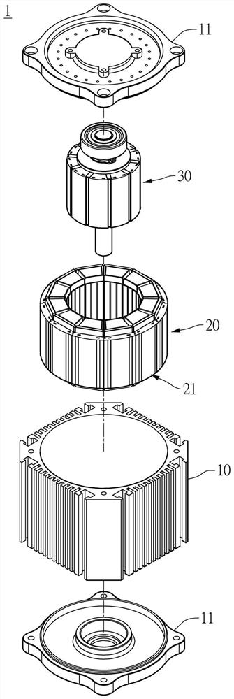
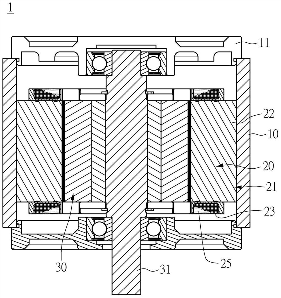
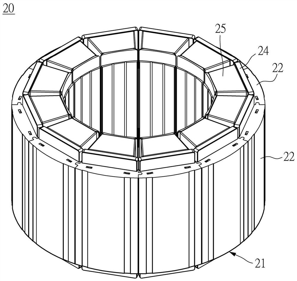
[0031] Such as Figure 1 to Figure 4 Shown is a motor 1 with the motor coil cooling structure of the present invention, wherein the motor includes a housing 10 , and a stator 20 and a rotor 30 disposed in the housing 10 . The stator 20 includes an iron core set 21 , the iron core set 21 is roughly in the shape of a ring, and the rotor 30 passes through the center of the iron core set 21 . Such as image 3 As shown, in this embodiment, the iron core group 21 of the stator 20 is composed of a plurality of iron core modules 22, and each iron core module 22 forms a winding portion 221 on the side facing the rotor 30, and each winding portion Winding slots 222 are respectively provided on both sides of the 221 , and the coil 23 is wound in the winding slots 222 of each winding portion 221 to form a plurality of armatures. The rotor 30 is disposed at the center of the stator 20 , and the rotor 30 has a rotating shaft 31 passing through an outer side of an end plate 11 of the housi...
no. 2 example
[0042] Such as Figure 9 to Figure 11 Shown is the second embodiment of the present invention, and the basic structure of the second embodiment of the present invention is similar to the technical features of the first embodiment, which will not be repeated in this description. The difference between the second embodiment of the present invention and the first embodiment is that the insulation structure between the coil 23 and the winding part 221 is changed to two sets respectively arranged on the winding part 221 on the longitudinal axis of the core module 22 The insulating cover 24 at both ends of the direction is formed. The two insulating sleeves 24 are sleeved on two ends of the winding portion 221 in the longitudinal axis direction of the core module 22 respectively, and the two insulating sleeves 24 respectively have two side plates 241 . The two insulating sleeves 24 are arranged at both ends of the winding portion 221 opposite to each other, and the ends of the two ...
no. 3 example
[0046] Such as Figure 12 to Figure 14 Shown is the third embodiment of the present invention. The feature of this embodiment is that it further includes a plurality of heat conducting components 40 and a heat dissipation device 50 . Wherein, the heat conduction component 40 of this embodiment may be a heat pipe, or a rod or cylinder made of copper metal. Each core module 22 has a connecting slot 26 for connecting the heat conducting component 40 . The plurality of heat-conducting components 40 respectively have a heat-absorbing end 41 and a cooling end 42 . The heat-absorbing end 41 of each heat-conducting component 40 is respectively inserted into the connecting groove 26 of the core module 22, and the cooling end 42 of each heat-conducting component 40 passes through an end plate 11 of the motor from the inside of the housing 10, and extends to the outside of the end plate 11. The heat dissipation device 50 is disposed on the outer side of the end plate 11 , and the cool...
PUM
 Abstract
Description
Claims
Application Information