
Energy-efficient automobile

a technology of energy-efficient automobiles and pulsed control signals, which is applied in the direction of driving parameters, position/direction control, braking systems, etc., can solve the problems of deteriorating energy efficiency, excessive prime mover motor power, and excessive external force, so as to reduce the pulse width of pulsed control signals, enhance the energy efficiency of automobiles, and reduce the effect of pulse width

Inactive Publication Date: 2012-03-27
RUSK INTELLECTUAL RESERVE
View PDF8 Cites 2 Cited by
  • Summary
  • Abstract
  • Description
  • Claims
  • Application Information

AI Technical Summary

Benefits of technology

"The present invention provides an automobile that can improve energy efficiency by preventing unnecessary consumption of fuel or energy in situations where the required motive power is less than the motive power corresponding to the accelerator-pedal depression amount. This is achieved by a controller that calculates a target operating amount of the energy-source supply system based on the accelerator-pedal depression amount detected by an accelerator pedal sensor, and outputs a continuous control signal to the energy-source supply system to actuate it. The controller can also convert the continuous control signal into a pulsed control signal with a predetermined pulse width, interpulse interval, and duty cycle, and output it to the energy-source supply system. The automobile can also detect the road surface slope, flatness, and wind velocity and direction, and use these factors to optimize energy efficiency."

Problems solved by technology

For example, when the automobile is traveling on a road surface having a relatively steep downward slope, or when a relatively strong tail wind is blowing to the automobile being traveling, an external force is applied to the automobile in a forward traveling direction thereof, and thereby the motive power of the prime mover becomes excessive by just as much as the external force.
Thus, the conventional automobile has a problem that fuel or energy is uselessly consumed in a situation where a required motive power is less than a motive power corresponding to an accelerator-pedal depression amount, resulting in deterioration in energy efficiency thereof.

Method used


Image

  • Energy-efficient automobile
  • Energy-efficient automobile
  • Energy-efficient automobile

Examples


Embodiment Construction

[0035]With reference to the accompanying drawings, the present invention will now be specifically described based on first to fourth embodiments thereof. The first embodiment relates to an automobile equipped with a spark-ignition engine as a prime mover, and the second embodiment relates to an automobile equipped with a diesel engine as the prime mover. Further, each of the third and fourth embodiments relates to an electric automobile equipped with an electric motor as the prime mover.

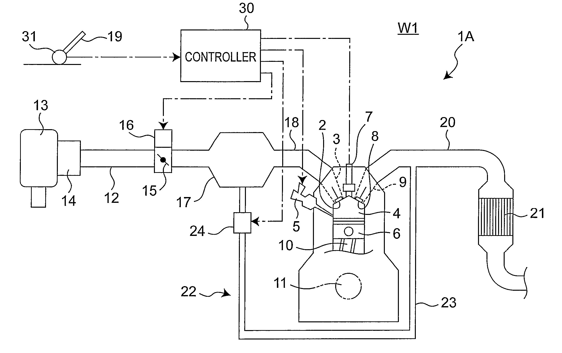
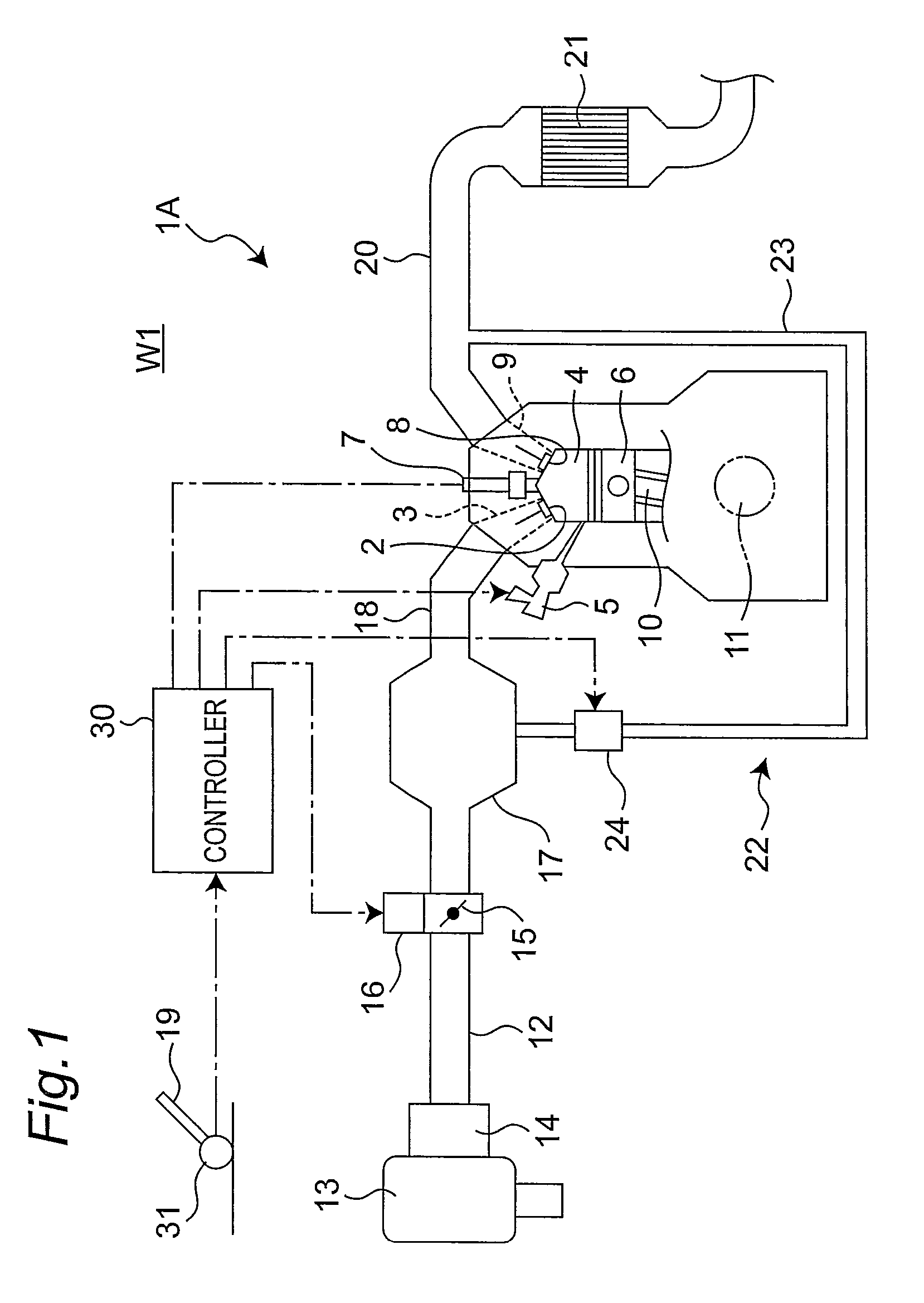
[0036](First Embodiment) As shown in FIG. 1, an automobile W1 according to the first embodiment is equipped with a spark-ignition multicylinder engine 1A using gasoline as fuel (only one of a plurality of cylinders is illustrated). In each of the cylinders of the engine 1A, when an intake valve 2 is opened during an intake stroke, air for combustion of fuel (combustion air) is sucked from an intake port 3 into a combustion chamber 4. Subsequently, at a given timing during a compression stroke, fuel i...


PUM


Abstract

Disclosed is an automobile equipped with an engine having an electronically-controlled throttle valve adapted to have an opening angle which is controlled according to an accelerator-pedal depression amount. The engine further includes an accelerator pedal sensor, an actuator adapted to selectively open and close the throttle valve, and a controller. The controller is adapted to calculate a target throttle opening angle corresponding to the accelerator-pedal depression amount, and output a continuous control signal corresponding to the target throttle opening angle, to the actuator. The controller is operable, in a traveling environment of the automobile or an operating condition of the engine where a required engine power is less than an engine power corresponding to the target throttle opening angle, to convert the continuous control signal into a pulsed control signal, and output the pulsed control signal to the actuator.

Description

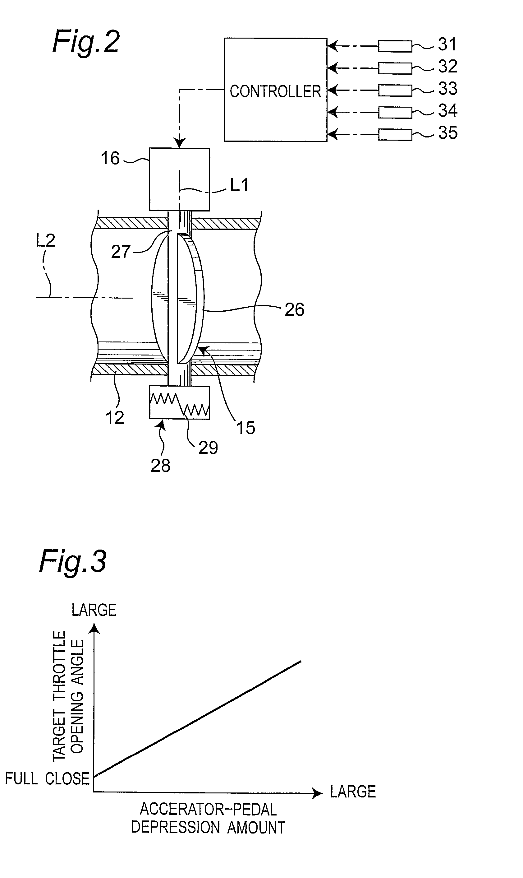
BACKGROUND OF THE INVENTION[0001]The present invention relates to an energy-efficient automobile adapted to reduce a motive-power generation amount of a prime mover, in a traveling environment or an operating condition where a motive power required for traveling is less than a motive power corresponding to an amount of depression of an accelerator pedal.[0002]Generally, in an automobile, a motive power to be generated by a prime mover is controlled by manipulating an accelerator pedal. For example, in an automobile equipped with a spark-ignition engine having an electronically-controlled throttle valve, a target opening angle of the throttle valve corresponding to an amount of depression of an accelerator pedal detected by an accelerator pedal sensor (the amount will hereinafter be referred to as “accelerator-pedal depression amount”) is calculated, and a control signal corresponding to the calculated target opening angle is output to an actuator of the throttle valve to control an ...

Claims


Application Information

Patent Timeline
Patent Type & Authority Patents(United States)
IPC IPC(8): F02D41/30G06F19/00
CPCB60L15/2045F02D11/106F02D41/107B60L2240/441B60L2240/445B60W2510/0638B60W2510/0676B60W2510/244B60W2540/10B60W2710/0605B60W2710/0616F02D2041/2027F02D2200/701F02D2200/702Y02T10/7283Y02T10/64Y02T10/72
Inventor UENO, RYUJI
Owner RUSK INTELLECTUAL RESERVE
Learn More