Concrete crack inducer with drainage channel

a technology of concrete crack inducer and drainage channel, which is applied in the direction of bridges, roads, roads, etc., can solve the problems of weak vertical plane of concrete, joint/crack will occur directly above the extrusion member, etc., and achieves the reduction of joint deflection and faulting, the effect of minimizing the opening width of the joint and smoothing the upper surfa

Active Publication Date: 2012-04-03
CONCRETE JOINT VENTURES
View PDF53 Cites 13 Cited by
  • Summary
  • Abstract
  • Description
  • Claims
  • Application Information

AI Technical Summary

Benefits of technology

[0016]The extruded member may include a notch for receiving a forming member, such as a 2×4. Smaller notches or holes may be made in the member for supporting re-bar and / or dowels to strengthen the concrete and concrete joints.
[0017]The extrusion members eliminate the need for saw cutting in the concrete, and eliminates the need for joint sealant in cut slots. The extrusions also prevent soft wet subgrade fines from being pumped upwardly through a formed joint, which can lead to faulting. The extrusions allow for horizontal movement of the concrete due to shrinkage and thermal volume changes. The extrusions provide a vertical support to transfer traffic loads across the joint, thereby reducing joint deflection and faulting. The extrusions minimize joint opening width at the concrete surface, which maximizes aggregate interlock and load transfer as traffic loading compresses the top of the joint. The minimized joint opening which results from use of the extrusions also provides for a smoother upper surface for the concrete. The minimal joint width above the extrusions also reduces traffic noise.

Problems solved by technology

After the extrusion is set in place, the concrete is poured over the extrusion, which causes a weak vertical plane in the concrete during the curing process.
As the concrete shrinks during curing, a joint / crack will occur directly above the extrusion member.
The extrusions also prevent soft wet subgrade fines from being pumped upwardly through a formed joint, which can lead to faulting.

Method used


Image

  • Concrete crack inducer with drainage channel
  • Concrete crack inducer with drainage channel
  • Concrete crack inducer with drainage channel

Examples


Embodiment Construction

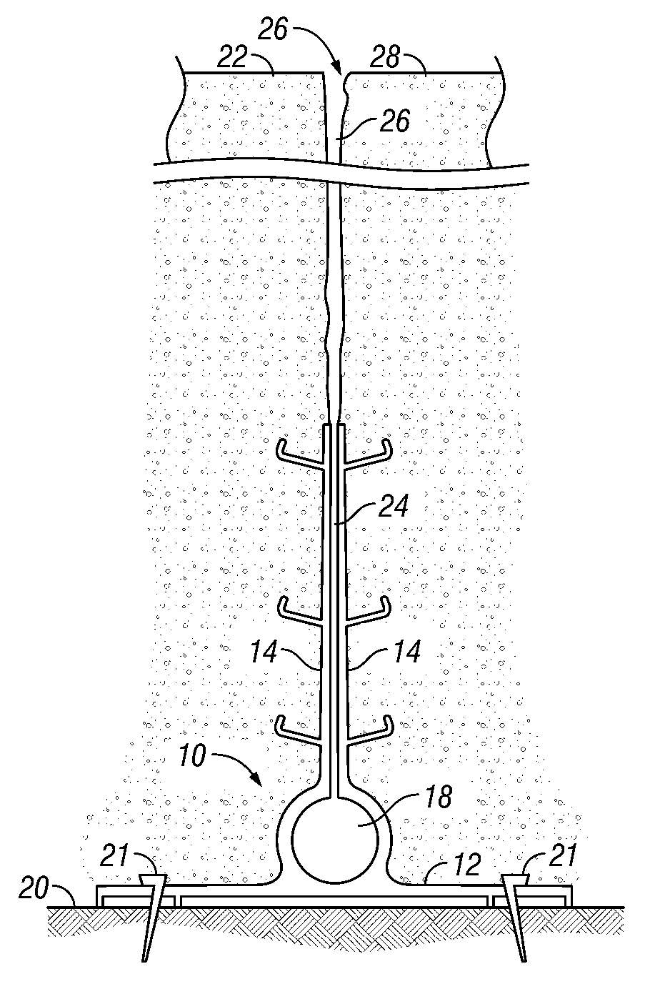
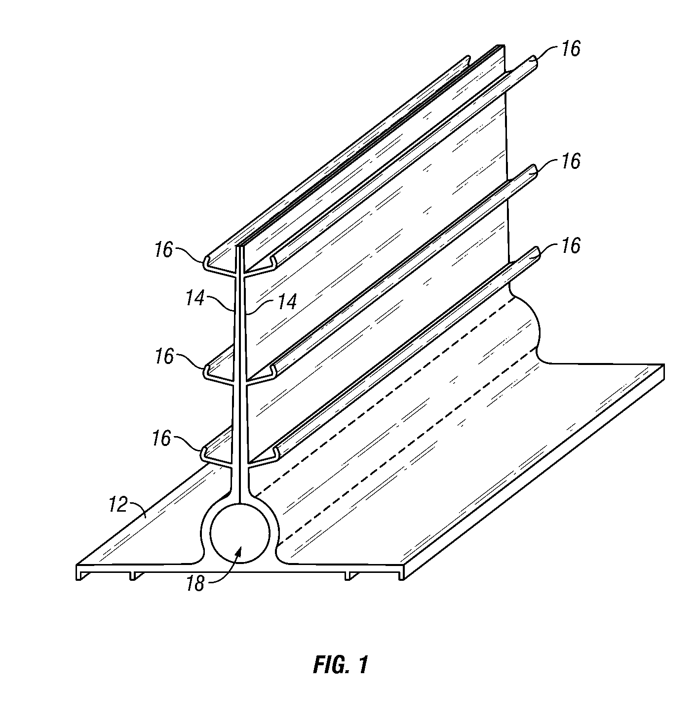
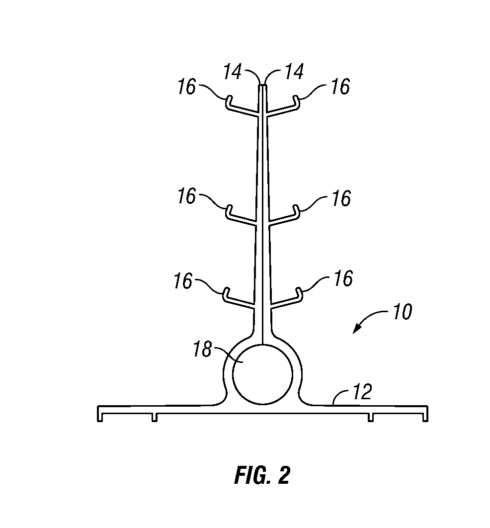
[0029]The concrete crack inducing and draining device 10 of the present invention is preferably an extruded plastic member having a base 12 and a pair of upstanding legs 14 which taper as they extend upward. In one embodiment, the device 10 has an inverted T-shape, as seen in FIGS. 1-4 and 8-10. In an alternative embodiment, the device 10A has an L-shape as seen in FIG. 5. A plurality of arms 16 extend outwardly from each leg. A drain channel 18 is formed in the member 10, 10A. In one embodiment, the drain channel 18 is adjacent the base 12, as seen in FIGS. 1-3, while in another embodiment the drain channel 18 is spaced above the base 12, as seen in FIGS. 4 and 5. As extruded, the legs 14 engage or abut one another, as seen in FIGS. 1, 2, 4 and 5.

[0030]The device 10, 10A is adapted for use in roadways, sidewalks, floor slabs, and other concrete environments. In use, the device 10, 10A is set upon the ground, subgrade, or road bed 20 upon which concrete is to be poured. The base 12 ...


PUM

PropertyMeasurementUnit
widthaaaaaaaaaa
lengthaaaaaaaaaa
right anglesaaaaaaaaaa

Abstract

A plastic extruded member is provided which will induce cracks in concrete and provide drainage for moisture entering the cracks. The member includes a base which sets upon the subgrade surface, with a pair of legs extending upwardly from the base. Arms extend laterally outwardly from each leg. As extruded, the legs are adjacent one another, and then spread apart as the concrete cures and shrinks, thereby inducing a substantially vertical crack in the concrete above the legs. The member includes a drain channel at the lower end of the legs. The gap between the legs which is created by the shrinking cured concrete provides a path from the crack to the drain channel for draining water entering the crack.

Description

CROSS-REFERENCE TO RELATED APPLICATIONS[0001]This application claims priority under 35 U.S.C. §119(e) to provisional application Ser. No. 60 / 979,214 filed Oct. 11, 2007, herein incorporated by reference in its entirety.BACKGROUND OF THE INVENTION[0002]After concrete is poured, it shrinks as it cures. Such shrinkage inherently causes cracking in the concrete at arbitrary locations and spacing. It is desirable to control the location of such cracking. For example, it is common to cut a slot in the upper surface of a partially cured roadway or sidewalk so as to force a crack beneath the cut. Sawing concrete is an extensive time and labor process. The cuts must be made at the proper time in the curing process, so as to avoid chipping of concrete around the soft cut, cracking at improper locations, and micro cracking around the saw cuts. The saw cuts must also be provided in the proper locations so as to avoid additional, undesirable cracking. Furthermore, saw cutting equipment, includin...

Claims


Application Information

Patent Timeline
Patent Type & Authority Patents(United States)
IPC IPC(8): E04B1/64
CPCE01C11/106E01C11/14E01C11/226E01D19/06E04B1/0007E04F15/142E01C2201/207E02D29/16
Inventor LOGEMANN, DAVID KEITHLOGEMANN, NEAL GENE
Owner CONCRETE JOINT VENTURES
Why Eureka
Try Eureka