Pneumatic mass transportation system

a technology of pneumatic mass transportation and mass transportation, applied in the direction of transportation and packaging, propulsion railway systems, transportation and packaging, etc., can solve the problems of unresolved problems inherent in the system, serious obstacles to practical development, and difficult control of power sources and prior art movemen

Active Publication Date: 2012-04-03
FLYNN PATRICK JOSEPH
View PDF47 Cites 12 Cited by
  • Summary
  • Abstract
  • Description
  • Claims
  • Application Information

AI Technical Summary

Benefits of technology

[0008]The PneuTrain is a unique supremely efficient rapid pneumatic mass transportation system. This system incorporates a free moving train of passenger cars through a tube infrastructure powered by a combination of differential air pressure forward and aft of the train. The train cars will be cylindrical. They will contact the tube surface via guide wheels. Air power for the system will be provided by stationary combustion turbines and heat recovery steam generators at both ends of the pneumatic tube run. Combustion turbines can be adapted to utilize alternative fuels including bio-fuels and fuel cell technology as they are explored and implemented. The integration of heat recovery steam generation recycles the hot turbine exhaust to generate the electrical power needed for the system's controls. Air propulsion is generated through the use of large impellers in the tubes driven by the turbines. Speed control, acceleration and deceleration are all digitally controlled by the conductor. The digital controls will vary the speed of the turbine engines, vary the pitch of the impeller blades and control the operation of the pressure release valves imbedded into the tube walls in direct relation to the throttle position and operation by the conductor.

Problems solved by technology

They are burdened with un-resolved issues inherent in pneumatic systems intended for use other than the transport of inanimate objects.
Power sources and control of movement of prior art have been problematic and present serious hindrances to practical development.
Other system concepts are plagued with friction-related drawbacks due to car travel on slides and tracks within the tube.

Method used


Image

  • Pneumatic mass transportation system
  • Pneumatic mass transportation system
  • Pneumatic mass transportation system

Examples


Embodiment Construction

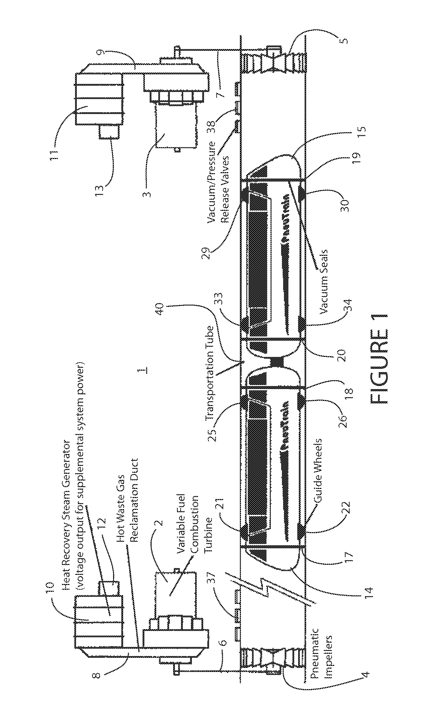
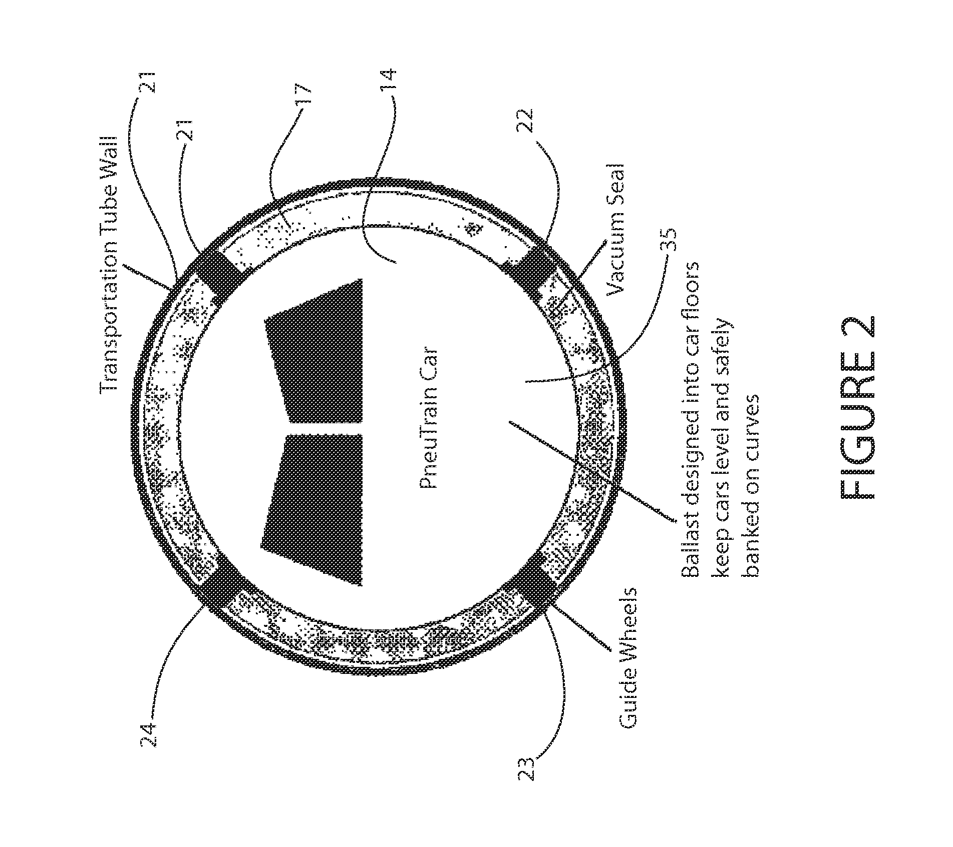
[0013]With reference to FIG. 1, the PneuTrain system 1 in concept utilizes as its power source the proven and energy efficient combination of combustion turbine technology married to a heat / exhaust recycling steam generator. This is exclusive to the PneuTrain 1. The main turbines 2, 3 will drive the impellers 4, 5 via a drive chain 6, 7. The turbines' 2, 3 hot exhaust gasses will enter a boiler 10, 11 via a duct 8, 9 to produce steam which in turn will power a steam turbine generator (heat recovery steam generation) 12, 13. This auxiliary power from reclaimed heat will be stored for use with the PneuTrain's 1 electrical system.

[0014]Clean natural gas is currently the fuel of choice to power the drive turbines. Natural gas is a very efficient fuel. It is also abundant in supply right here in the United States. Additionally, with reference to FIG. 1, the combustion turbine is a versatile power source to physically drive the pneumatic impellers 3, 4 of the PneuTrain system. The technol...


PUM


Abstract

A pneumatic mass transportation system employs a combined cycle turbine power system with digital controls to effect acceleration, deceleration and train propulsion. Combustion turbines can be adapted to use alternative fuels including bio fuels as they are developed. A heat recover steam generator recycles hot exhaust gasses from turbines to generate electricity to be used by the system. A multi-car train is propelled by differential air pressure forward and aft of the vehicle in a pneumatic tube. Air propulsion is achieved by large in-tube impellers driven by the turbines. A digital control system controls turbine speed, pitch of impeller blades and vacuum / pressure release valves in the tubes to maneuver and control the train.

Description

REFERENCE TO RELATED APPLICATIONS[0001]This invention claims priority to U.S. Provisional Patent Application No. 61 / 195,509 of the same title and filed Oct. 8, 2008, the entirety of which is hereby incorporated by reference.FEDERALLY SPONSORED RESEARCH OR DEVELOPMENT[0002]Not applicable.REFERENCE TO SEQUENCE LISTING[0003]Not applicable.BACKGROUND[0004]1. Field of Invention[0005]The need is imperative to develop new forms of safe, alternative transportation that are supremely energy efficient. This invention represents a unique approach to pneumatic ground transportation for passengers and cargo. The system's power source, method of propulsion and controls are exclusive elements to this invention.[0006]2. Description of Prior Art[0007]Pneumatic passenger systems have been conceived to date. They are burdened with un-resolved issues inherent in pneumatic systems intended for use other than the transport of inanimate objects. Power sources and control of movement of prior art have been...

Claims


Application Information

Patent Timeline
Patent Type & Authority Patents(United States)
IPC IPC(8): B61B13/10
CPCB61B13/10
Inventor FLYNN, PATRICK JOSEPH
Owner FLYNN PATRICK JOSEPH
Why Eureka
Try Eureka