Super Cooled Air And Fuel Induction System For Internal Combustion Engines

a fuel induction system and super cooling technology, applied in the field of internal combustion engines, to achieve the effect of minimizing the use of alternative fuels, improving performance programming, and maximizing fuel efficiency

Active Publication Date: 2009-05-21
DYNAMIC FUEL SYST
View PDF28 Cites 29 Cited by
  • Summary
  • Abstract
  • Description
  • Claims
  • Application Information

AI Technical Summary

Benefits of technology

[0015]Briefly, the present invention is directed toward a system for injecting a secondary fuel to a diesel engine wherein the secondary fuel is also utilized to cool or super cool the incoming air charge to the engine. The preferred embodiment of the propane injector system comprises introducing liquid propane into “a chiller assembly” whereby the incoming air charge passes through the chiller assembly to warm the liquid propane, converting it to a gaseous state as the incoming air charge is cooled. The gaseous propane is then routed to a black box that includes a pressure reducing valve to drop propane pressure as it flows initially from the chiller assembly and through an electronically controlled on/off valve. The gaseous propane enters an injector manifold where it is distributed to at least one, more preferably two, but as many as required, specially designed gas handling fuel injectors that act as variable flow rate injectors controlled by a programmable microprocessor that is pre-programmed for specific vehicles or can be customized with improved performance programming as determined by the vehicle owner. The number of fuel injectors utilized depends on the different size of

Problems solved by technology

The only limitation regarding the number of fuel injectors utilized is

Method used


Image

  • Super Cooled Air And Fuel Induction System For Internal Combustion Engines
  • Super Cooled Air And Fuel Induction System For Internal Combustion Engines
  • Super Cooled Air And Fuel Induction System For Internal Combustion Engines

Examples


Embodiment Construction

[0035]While the present invention is susceptible of embodiment in various forms, there is shown in the drawings and will hereinafter be described a presently preferred embodiment with the understanding that the present disclosure is to be considered an exemplification of the invention and is not intended to limit the invention to the specific embodiments illustrated.

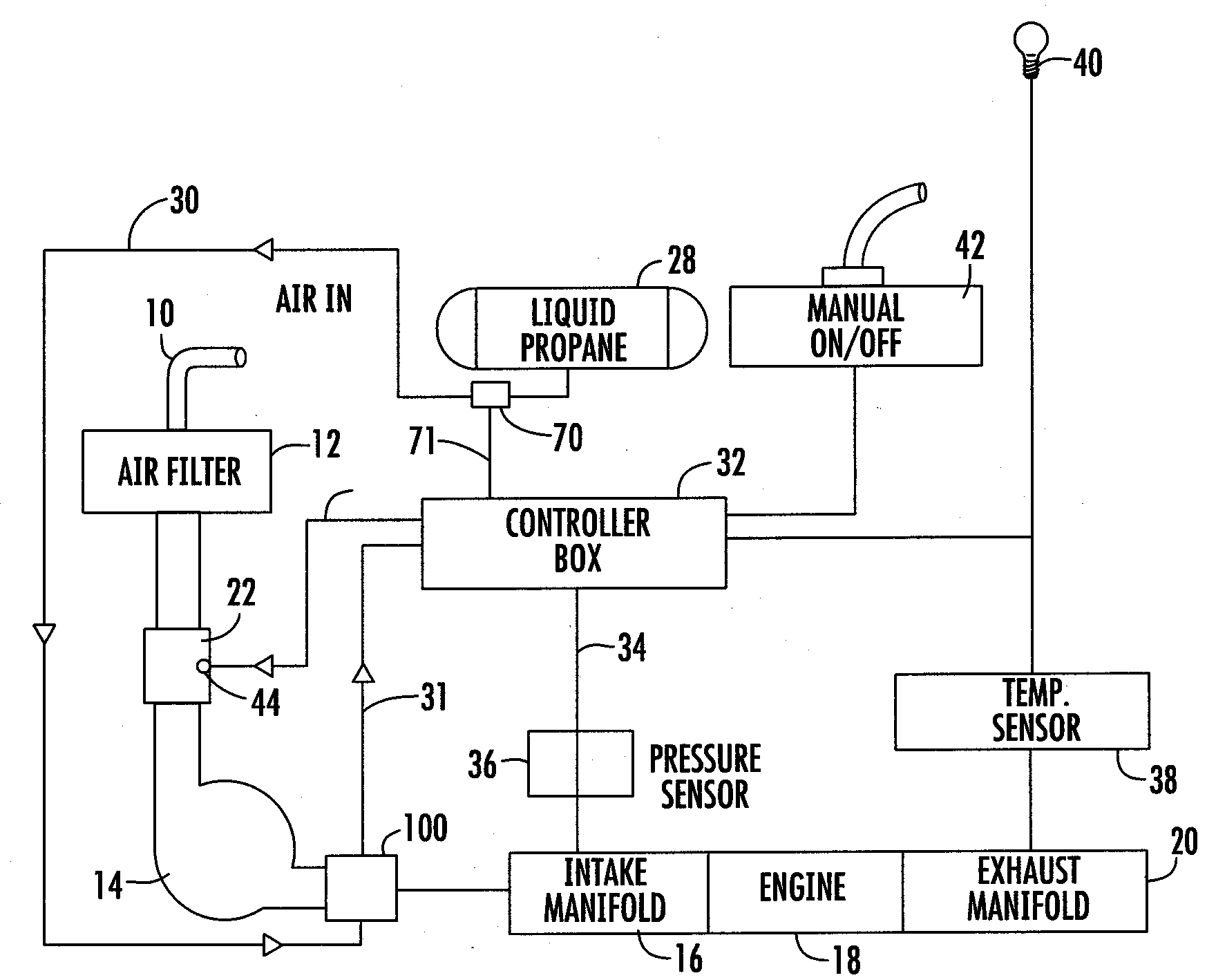
[0036]The different types of internal combustion engines that can be used in conjunction with the supplemental fuel system include but are not limited to diesel engines, internal combustion engines in vehicles, stationary internal combustion engines, internal combustion engines in locomotives, internal combustion engines in marine vessels, and internal combustion engines in aircraft. The supplemental fuels used in conjunction with this system include but are not limited to liquid propane, propane, liquefied natural gas, natural gas, liquid butane, butane, and MAP gas.

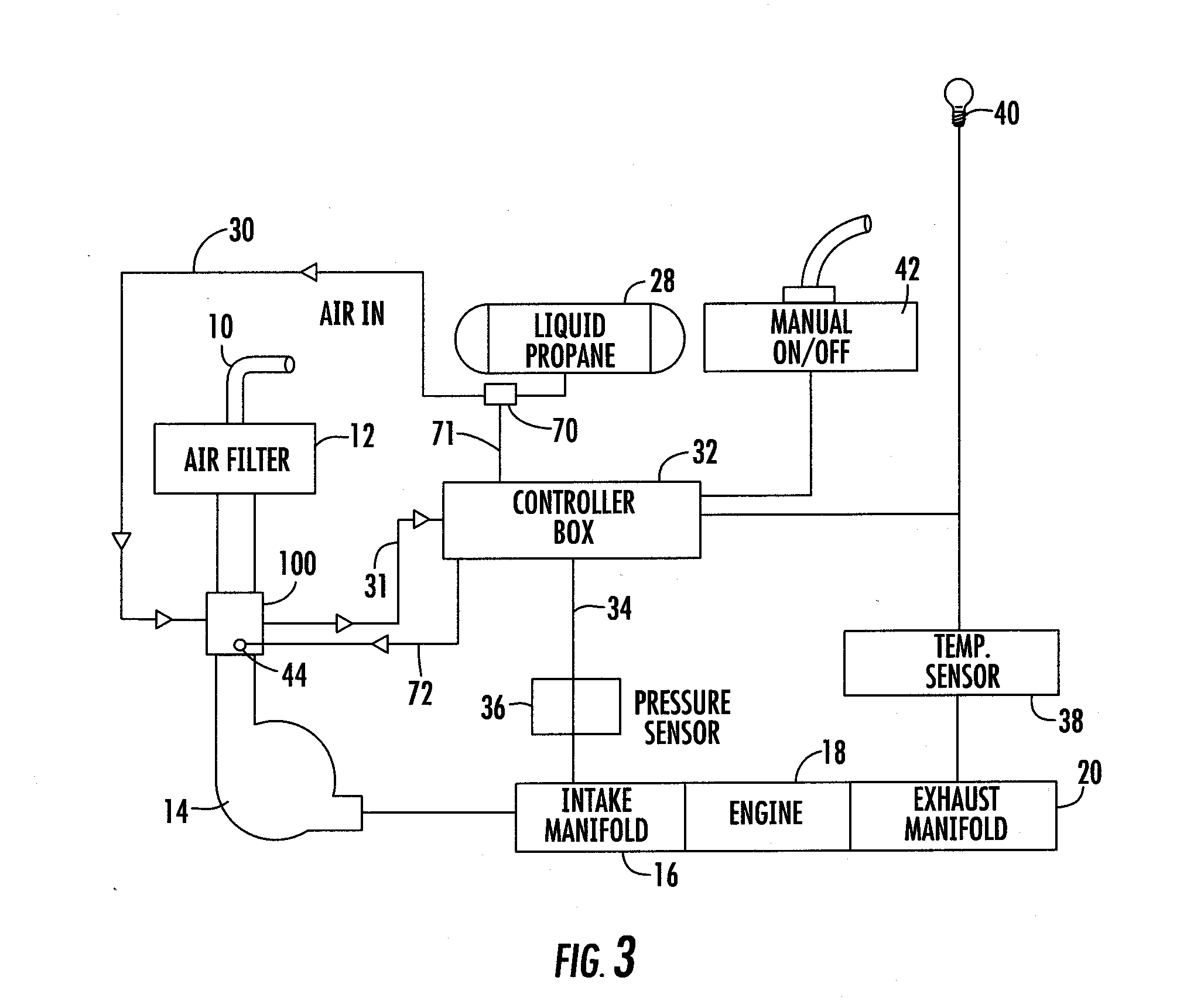
[0037]Referring generally to FIGS. 1 and 3, a schemati...


PUM


Abstract

The instant invention provides an apparatus and system for cooling the air charge of an internal combustion engine. More specifically, the instant invention provides an air-induction system suitable to provide cooled air charges to turbocharged, supercharged or naturally aspirated internal combustion engines to increase power output while reducing engine emissions. The system utilizes gaseous fuel stored as a liquid wherein the liquefied gaseous fuel is vaporized and warmed at least partially with heat removed from the intake air charge supplied to the engine from the turbocharger or supercharger. In a preferred embodiment, the compressed intake combustion air is first cooled in an aftercooler against an ambiently cooled coolant and is subsequently cooled further by the chiller of the instant invention which utilizes the change in phase, between liquid and gas, of the alternative fuel to cool the incoming air charge. The fuel, in the gaseous phase, is then supplied to the engine in a controlled manner for combustion by the engine. The operation of this system is measured and controlled by a control box mounted in the engine compartment.

Description

CROSS-REFERENCE TO RELATED APPLICATIONS[0001]This application is related to U.S. Pat. No. 7,100,582, entitled Propane Injection Control System and Apparatus for Vehicles, the contents of which are incorporated herein by reference. This application also claims the benefit under 35 U.S.C. 119(e) of U.S. Provisional Patent Application No. 60 / 988,539, filed Nov. 16, 2007, entitled SUPERCOOLED AIR INDUCTION SYSTEM FOR INTERNAL COMBUSTION ENGINES, the entirety of which is incorporated herein by reference.FIELD OF INVENTION[0002]The present invention generally relates to internal combustion engines, and more particularly, to an apparatus and method of super cooling the air charge of an internal combustion engine.BACKGROUND INFORMATION[0003]For more than a century, internal combustion engines have been relied upon as a principal source of power in a variety of applications. Of those engines, the most widely used are the reciprocating piston engines which are found in automobiles or other fo...

Claims


Application Information

Patent Timeline
IPC IPC(8): F02D41/30
CPCF02B29/0418F02D19/027F02B29/0475F02B33/00F02B37/00F02D19/0631F02D19/0647F02D19/066F02D19/0668F02D19/10F02D41/0025F02D41/1446F02D41/34F02M21/0287Y02T10/146Y02T10/36Y02T10/144Y02T10/32F02D19/081F02M21/042F02B29/0437Y02T10/12Y02T10/30
Inventor BACH, JEFF
Owner DYNAMIC FUEL SYST
Why Eureka
Try Eureka