Clutch control system for saddle riding type vehicle

a technology of clutch control system and saddle riding, which is applied in the direction of analogue processes for specific applications, instruments, cycles, etc., can solve the problem of not being able to identify correctly the grip condition of tires, and achieve the effect of reducing the transmission force of the clutch

Active Publication Date: 2012-04-03
HONDA MOTOR CO LTD
View PDF16 Cites 5 Cited by
  • Summary
  • Abstract
  • Description
  • Claims
  • Application Information

AI Technical Summary

Benefits of technology

[0007]According to an embodiment of the present invention, the clutch control system includes a clutch, an actuator, a driving wheel speed detection means, a driven wheel speed detection means, and an actuator control means. More specifically, the clutch connects and disconnects a driving force from an engine relative to a driving wheel. The actuator causes the clutch to engage or disengage. The driving wheel speed detection means detects a driving wheel peripheral speed in the driving wheel. The driven wheel speed detection means detects a driven wheel peripheral speed in a driven wheel. The actuator control means controls the actuator based on the driving wheel peripheral speed obtained from the driving wheel speed detection means and the driven wheel peripheral speed obtained from the driven wheel speed detection means. Further, the actuator control means reduces a transmission force of the clutch when the driving wheel peripheral speed is lower than the driven wheel peripheral speed and an absolute value of a difference between the driving wheel peripheral speed and the driven wheel peripheral speed is greater than a first threshold value.
[0008]As such, the decision made based on the driving wheel peripheral speed and the driven wheel peripheral speed allows an actual condition of the saddle riding type vehicle to be identified. This enables clutch control with appropriate in a timely manner, so that a grip force of the driving wheel can be appropriately maintained.
[0009]According to an embodiment of the present invention, the clutch control system further includes an engine control means. The engine control means reduces an output of the engine when the driving wheel peripheral speed is higher than the driven wheel peripheral speed and an absolute value of a difference between the driving wheel peripheral speed and the driven wheel peripheral speed is greater than a second threshold value.
[0014]As such, when the inclination angle of the saddle riding type vehicle is fairly large, it can be determined that the vehicle is turning. Then, appropriate clutch control according to the turning is provided and the grip force of the driving wheel can be maintained appropriately.
[0016]As such, when the inclination angle of the saddle riding type vehicle is fairly large, it can be determined that the vehicle is turning. Then, the output of the engine is controlled appropriately according to the turning and the grip force of the driving wheel can be maintained even more appropriately.

Problems solved by technology

As a result, the means of estimation using the parameter indicating the vehicle operating condition may not be able to identify correctly the tire grip condition.

Method used


Image

  • Clutch control system for saddle riding type vehicle
  • Clutch control system for saddle riding type vehicle
  • Clutch control system for saddle riding type vehicle

Examples


Embodiment Construction

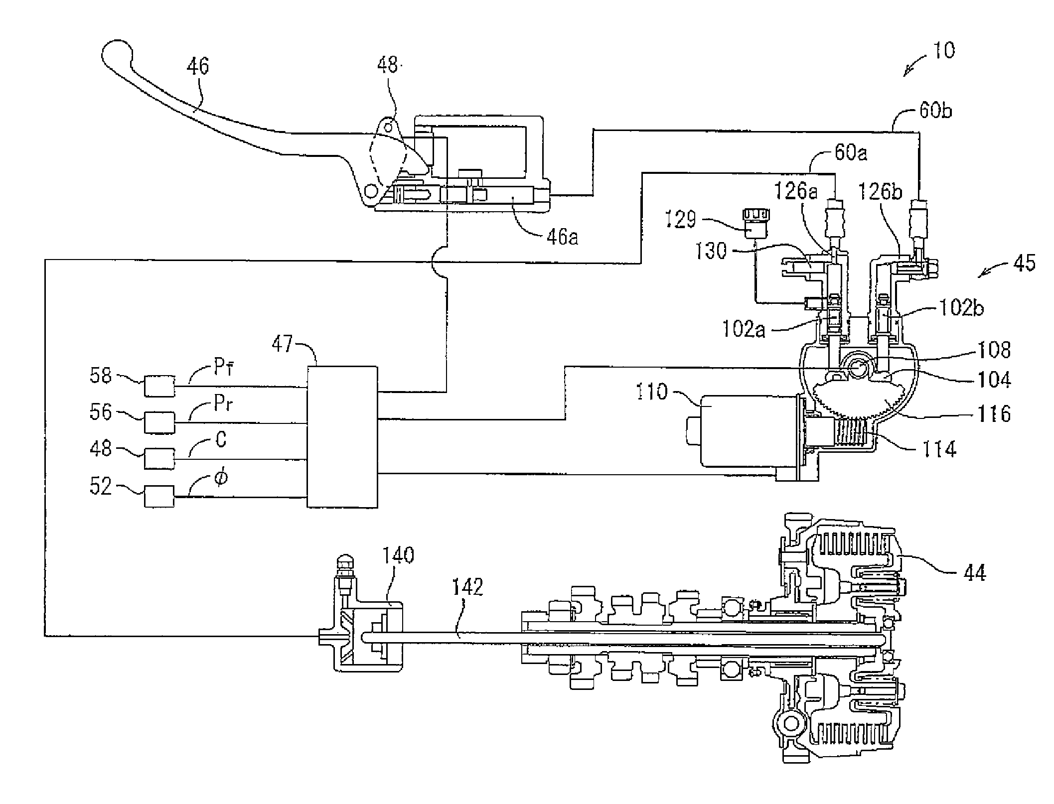
[0027]A clutch control system for a saddle riding type vehicle according to a specific embodiment to which the present invention is applied will be described below with reference to the accompanying FIGS. 1 through 7. A clutch control system 10 according to the embodiment of the present invention is mounted on a motorcycle 11. The motorcycle 11 will first be described below.

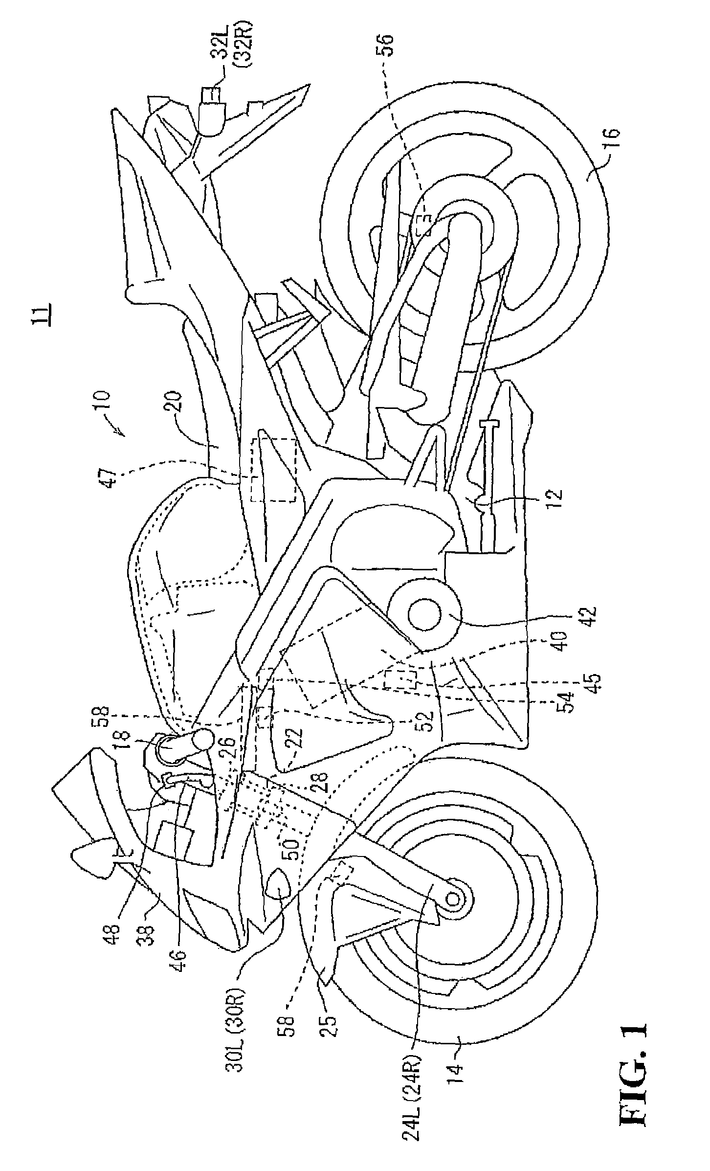
[0028]The embodiment of the present invention will be illustrated as being applied to a full cowling type motorcycle 11 (saddle riding type vehicle) as shown in FIG. 1. The embodiment is nonetheless only illustrative and is applicable to a saddle riding type vehicle of a different type (for example, a scooter, a buggy, or the like). In the motorcycle 11, a pair of left and right mechanisms or elements symmetrically disposed on a body of the motorcycle 11 will be identified by reference numerals appended with “L” for the left one and “R” for the right one. In the descriptions that follow, “right” refers to the rig...


PUM


Abstract

A grip force of a driving wheel is maintained by identifying an actual condition of a motorcycle and controlling a clutch in a timely manner. A clutch control system includes a clutch, an actuator unit causing the clutch to engage or disengage, a rear wheel speed sensor, a front wheel speed sensor, a clutch lever sensor and a controller controlling a control motor based on a rear wheel speed and a front wheel speed. When the rear wheel speed is lower than the front wheel speed and an absolute value of a difference between the rear wheel speed and the front wheel speed is greater than a threshold value, the control motor is driven so as to reduce a transmission force of the clutch. When an operational amount of the clutch lever is greater than a threshold value, processing to reduce the transmission force of the clutch is suspended.

Description

CROSS-REFERENCE TO RELATED APPLICATIONS[0001]The present application claims priority under 35 USC 119 to Japanese Patent Application No. 2007-251325 filed on Sep. 27, 2007 the entire contents of which are hereby incorporated by reference.FIELD OF THE INVENTION[0002]The present invention relates to a clutch control system for a saddle riding type vehicle, the system including a clutch connecting and disconnecting a driving force from an engine relative to a driving wheel, an actuator causing the clutch to engage or disengage, and an actuator control means controlling the actuator.DESCRIPTION OF BACKGROUND ART[0003]In general with regard to motorcycles an output from an engine is transmitted to a driving wheel via a clutch. An engine brake is applied when sudden downshifting is carried out or on a similar occasion, resulting in a decrease in a grip force from a road surface. The driving wheel may at times run idle due to a reduced tire grip force. To respond to such situations occurri...

Claims


Application Information

Patent Timeline
Patent Type & Authority Patents(United States)
IPC IPC(8): B60W10/02G06F7/00G06F17/00G06F19/00B60W10/04
CPCB60W10/02B60W10/06B60W30/18172F16D48/066B60W2540/14B60Y2200/12Y10T477/755F16D2500/1117F16D2500/3115F16D2500/5075Y10T477/79Y10T477/78Y10T477/753F16D2500/10412
Inventor IWASHITA, KANAUTOMODA, AKIHIKO
Owner HONDA MOTOR CO LTD
Why Eureka
Try Eureka