Power storage apparatus

a power storage and power technology, applied in the direction of battery/fuel cell control arrangement, cell components, capacitor propulsion, etc., can solve the problems of accelerating deterioration in the insulator extremely short life of etc., to reduce the voltage to ground at given positions in the power storage apparatus, suppress the progress of deterioration in the insulator, and reduce the voltage across the insulator (unillustrated).

Inactive Publication Date: 2012-04-03
MITSUBISHI ELECTRIC CORP
View PDF6 Cites 2 Cited by
  • Summary
  • Abstract
  • Description
  • Claims
  • Application Information

AI Technical Summary

Benefits of technology

[0006]The present invention provides a power storage apparatus that lowers the voltage to ground therein while being in the stop mode so as to suppress the deterioration in the insulators, thereby allowing the insulation treatment during repair and maintenance to be simplified.
[0008]In the case where the power storage apparatus is not operated, the voltages to ground at given positions in the power storage apparatus can be lowered; therefore, the voltages across the insulators (unillustrated) in the apparatus can be reduced, whereby the progress of the deterioration in the insulators can be suppressed.

Problems solved by technology

Meanwhile, in the case where the power storage device is applied to an electric railway system, a great number of modules are connected in series; the voltage to ground thereof is as high as 750 V to 1500 V. When, among power storage devices, a secondary battery, in particular, is completely discharged, the lifetime thereof becomes extremely short; therefore, even while the power storage system is not in operation, the power storage device is left charged, whereby the voltage to ground is maintained as high as 750 V to 1500 V. Accordingly, it has been a problem that the deterioration in the insulators in the power storage apparatus is accelerated due to a long-term charging; in addition to that, during repair and maintenance of the power storage apparatus, stringent insulation treatment is required.

Method used


Image

  • Power storage apparatus
  • Power storage apparatus
  • Power storage apparatus

Examples


embodiment 1

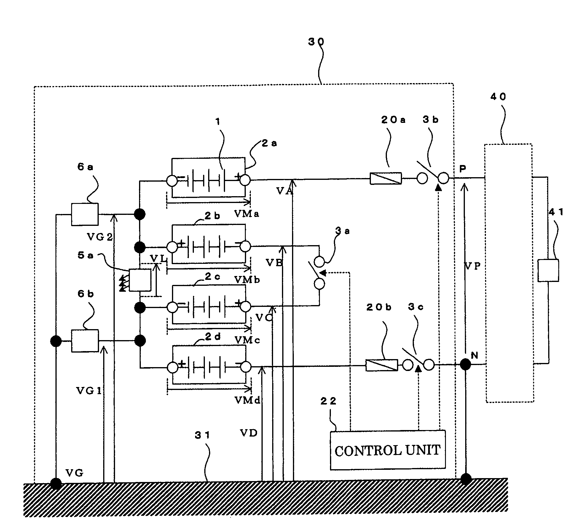
[0013]FIG. 1 is a diagram illustrating a configuration example of a power storage apparatus according to Embodiment 1 of the present invention. The configuration of a power storage apparatus 30 will be explained with reference to FIG. 1. As illustrated in FIG. 1, modules 2a to 2d, in each of which cells 1 are connected in a series-parallel fashion, are connected in series. A switch 3a (a second switch) is provided between the negative electrode terminal of the module 2b and the positive electrode terminal of the module 2c, thereby dividing the modules 2a to 2d into two groups, i.e., a group of the modules 2a and 2b and a group of the modules 2c and 2d. Additionally, a display device 5a is provided between the positive electrode terminal of the module 2b and the negative electrode terminal of the module 2c. In this case, the display device 5a, which is a device for visually indicating whether or not a voltage exists, by, e.g., blinking an LED, operates when a specific voltage is gene...

embodiment 2

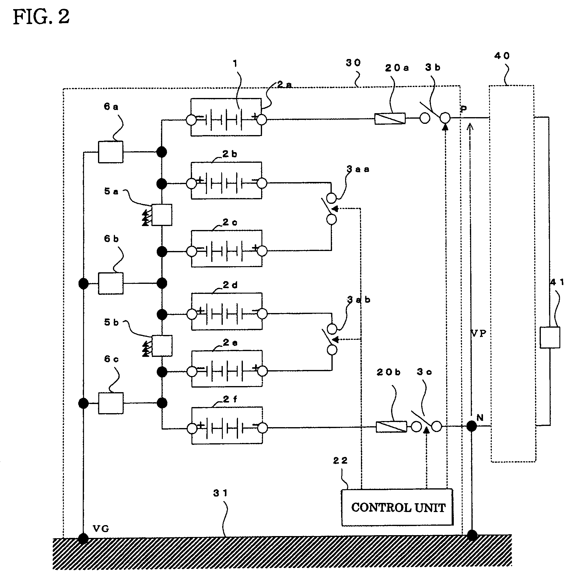
[0045]FIG. 2 is a diagram illustrating a configuration example of a power storage apparatus according to Embodiment 2 of the present invention. FIG. 2 illustrates a configuration example in the case where the number of modules is six; the configuration is in such a way that modules 2e and 2f are added. In contrast to FIG. 1 which illustrates a case in which the number of modules is four, the configuration is in such a way that a switch 3ab is connected between the negative electrode of the module 2d and the positive electrode of the module 2e, a display device 5b is connected between the positive electrode of the module 2d and the negative electrode of the module 2e, and the connection point where the module 2e and the module 2f are connected is grounded to the reference electric potential plane 31, by way of a grounding resistor 6c.

[0046]As far as the operation is concerned, in the case where the number of modules is six, the explanation is the same as that for the case where the ...

embodiment 3

[0047]FIG. 3 is a diagram illustrating a configuration example of a power storage apparatus according to Embodiment 3 of the present invention. FIG. 3 is a diagram illustrating a configuration example in the case where the number of modules is two. The same reference characters in FIG. 3 denote the same or equivalent constituent elements as those in FIGS. 1 and 2. In the case where the number of modules is two, the configuration is in such a way that the connection point where the modules 2a and 2b are connected is connected to the reference electric potential plane 31, by way of the grounding resistor 6a. With the configuration according to Embodiment 3, the maximal voltage to ground in the power storage apparatus is VP while the apparatus is operated; the maximal voltage to ground in the power storage apparatus is half of VP while the apparatus is not operated.

[0048]As described above, with configurations in Embodiments 1 to 3 of the present invention, in the case where the power ...


PUM

PropertyMeasurementUnit
voltageaaaaaaaaaa
voltage VMaaaaaaaaaa
voltagesaaaaaaaaaa

Abstract

In a power storage apparatus, for storing DC electric power, which is configured by connecting in series a plurality of modules each including a plurality of cells connected with one another, by providing two first switches at the input portion and at the output portion of the power storage apparatus and a second switch, in series with the modules, at a connection position where the modules are connected, the voltage to ground in the apparatus is lowered.

Description

TECHNICAL FIELD[0001]The preset invention relates to a power storage apparatus for storing DC electric power, and, for example, to a power storage apparatus that can be applied to an electric rolling stock or the like equipped with a power storage system.BACKGROUND ART[0002]To date, it has been known that, by applying a power storage device, such as a secondary battery or an electric double layer capacitor, to an electric railway system so as to configure the electric railway system in such away that superfluous regenerative electric power generated while the vehicle is braked (during a regenerative period) is stored in the power storage device and the stored electric power is utilized while the vehicle is accelerated (during a power running period), the kinetic energy of the vehicle can effectively be utilized (e.g., Non-Patent Document 1).[Non-Patent Document 1][0003]Institute of Electrical Engineers of Japan, national convention 5-176, 2005, “Development of Power Storage System f...

Claims


Application Information

Patent Timeline
Patent Type & Authority Patents(United States)
IPC IPC(8): H01M6/42H01M2/00H01M2/10
CPCB60L7/12B60L3/0046B60L3/0069B60L11/005B60L11/1864B60L11/1853B60L2200/26Y02T10/7005Y02T10/7022Y02T10/7061B60L50/40B60L58/18B60L58/21Y02T10/70H02J7/34
Inventor KITANAKA, HIDETOSHI
Owner MITSUBISHI ELECTRIC CORP
Why Eureka
Try Eureka