Image capture apparatus, control method thereof, program, and storage medium
a technology of image capture and control method, applied in the direction of exposure control, color signal processing circuit, instruments, etc., can solve the problems of difficulty in determining the actual exposure value, the actual exposure value may deviate from the correct exposure value, and the difficulty of performing accurate correction for every interchangeable lens, so as to eliminate the influence of an error
- Summary
- Abstract
- Description
- Claims
- Application Information
AI Technical Summary
Benefits of technology
Problems solved by technology
Method used
Image


Examples
first embodiment
[0026]FIG. 1 is a block diagram schematically illustrating the configuration of a single-lens reflex camera according to a first embodiment of the invention, on which a plurality of types of interchangeable lenses is selectively mounted.
[0027]Referring to FIG. 1, the camera includes a camera body 10 and an interchangeable lens 30. The interchangeable lens 30 is detachably mounted on the camera body 10. The camera body 10 and the interchangeable lens 30 are electrically coupled with each other via contacts (not shown). The interchangeable lens 30 includes at least a diaphragm 31.
[0028]The camera body 10 includes a mirror 11, a shutter 12 and an image sensor 13. The image sensor 13 is a solid-state image sensor such as a CCD (charge-coupled device) sensor. The mirror 11 is configured to flip upward so as to allow light passing through the interchangeable lens 30 to reach the image sensor 13 during an image capture operation. The image sensor 13 is not limited to a CCD sensor but may b...
second embodiment
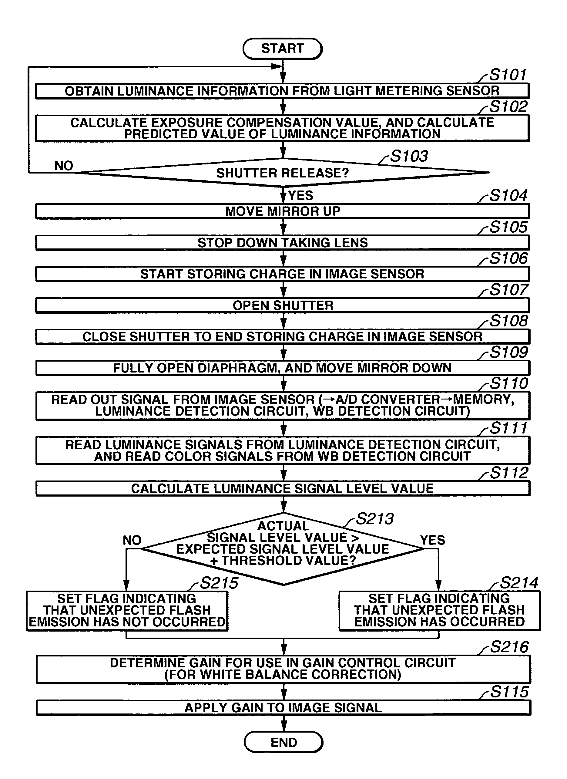
[0061]FIG. 6 is a flow chart illustrating the image capture sequence of a camera according to a second embodiment of the invention. In FIG. 6, steps for performing the same processing operations as those in the first embodiment are assigned the same step numbers as those in FIG. 5.
[0062]The second embodiment differs from the first embodiment in that, while the first embodiment is configured to correct luminance by controlling the gain, the second embodiment is configured to correct white balance by controlling the gain.
[0063]In the flow chart of FIG. 6, steps S113 and S114 shown in FIG. 5 are replaced by steps S213 to S216, which are discussed below.
[0064]At step S213, the microcomputer 17 makes a comparison to determine if the luminance signal level value calculated at step S112 is greater than a value obtained by adding a predetermined threshold value to the expected signal level value calculated or estimated at step S102. If the calculated luminance signal level value is greater,...
third embodiment
[0069]FIG. 7 is a flow chart illustrating the image capture sequence of a camera according to a third embodiment of the invention. In FIG. 7, steps for performing the same processing operations as those in the second embodiment are assigned the same step numbers as those in FIG. 6.
[0070]The third embodiment differs from the second embodiment in that, while the second embodiment is configured to correct white balance by controlling the gain in accordance with the magnitude relation between the actual signal level value and the expected signal level value, the third embodiment is configured to correct white balance by controlling the gain in accordance with the ratio of the actual signal level value to the expected signal level value.
[0071]In the flow chart of FIG. 7, steps S213, S214 and S215 shown in FIG. 6 are replaced by steps S313 and S314, which are discussed below.
[0072]At step S313, the microcomputer 17 obtains the ratio of the actual signal level value obtained from the image...
PUM
 Abstract
Description
Claims
Application Information