Coded aperture snapshot spectral imager and method therefor

a spectral imager and coded aperture technology, applied in the field of spectral imaging, can solve the problems of high light input, poor signal-to-noise ratio, and the inability to particularly apply the imager to imaging non-static scenes

Active Publication Date: 2012-04-03
DUKE UNIV +1
View PDF15 Cites 7 Cited by
  • Summary
  • Abstract
  • Description
  • Claims
  • Application Information

AI Technical Summary

Benefits of technology

[0013]In particular, the illustrative embodiment of the present invention processes light from a scene to provide a spatio-spectral map (i.e., a spectral image) of the scene. The light, which comprises a plurality of spectral components, is processed through an optical system that includes a sparse-coded aperture having a plurality of transmissive regions. The optical system provides a plurality of images of the scene on a detector image plane. These images are interspersed on the detector image plane, and each of the images is characterized by only one of the plurality of spectral components. A photodetector array is located at the detector image plane and each photodetector in the array receives light that has only one of the plurality of spectral components. As result, computation of the spatio-spectral datacube that describes the scene is relatively simple as compared to that required in prior-art spectral imagers. The present invention, therefore, enables rapid spectral imaging of the scene.
[0018]In some embodiments, the scene is imaged onto a first sparse-coded aperture, which is imaged onto a second sparse-coded aperture through a first disperser. As a result, the spectral components from each transmissive region of the first coded aperture are spatially dispersed along a first dimension on the second coded aperture, wherein the first dimension is substantially aligned with the rows of the first and second coded apertures. The second coded aperture “combs” the dispersed spectral components from the first coded aperture to create very narrow channel widths for each spectral component. Finally, the second coded aperture is imaged onto the detector image plane through a second disperser. The second disperser removes some, but not all, of the dispersion introduced by the first disperser.
[0019]In some embodiments, a plurality of lenses, such as a lenslet array, is used to image a first image plane (e.g., a sparse-coded aperture) onto a second image plane (e.g., the detector image plane). Each of the plurality of lenses images a different area of the first image plane. Such embodiments mitigate the challenges of lens design associated with large aperture lenses and allow for more compact optical systems. As a result, these embodiments can further reduce the complexity, cost, and volume of spectral imagers.

Problems solved by technology

Unfortunately, tomographic spectral imagers are very slow since each image must be acquired while the scene is substantially static.
Further, the geometry of such systems normally limits the range of angles over which the dispersive element can be rotated and, therefore, the number of spectral components that can be included in the datacube.
Such imagers typically require high light input and have very poor signal-to-noise ratios.
Further, such imagers are not particularly applicable for imaging non-static scenes.
While a snap-shot imager acquires all of the desired spectral information of a scene simultaneously, the unraveling (i.e., demultiplexing) the multiple projections to assemble the datacube can be quite computationally complex.
As a result, spectral image computation time can be time-consuming.
This limits the operation rate for such spectral imagers, which precludes their use in many high-speed imaging applications.

Method used


Image

  • Coded aperture snapshot spectral imager and method therefor
  • Coded aperture snapshot spectral imager and method therefor
  • Coded aperture snapshot spectral imager and method therefor

Examples


Embodiment Construction

[0033]The following terms are defined for use in this Specification, including the appended claims:[0034]Plurality of spectral components is defined as those spectral components of interest for the development of a datacube. In some cases, light might include additional spectral components beyond those pertinent to the development of the datacube. These additional spectral components are disregarded, vis-à-vis the use of the term “plurality of spectral components.”[0035]Transmissive is defined as substantially transparent for the plurality of spectral components. For example, a transmissive region passes light characterized by any of the plurality of spectral components without significant attenuation.[0036]Non-transmissive is defined as substantially opaque for the plurality of spectral components.

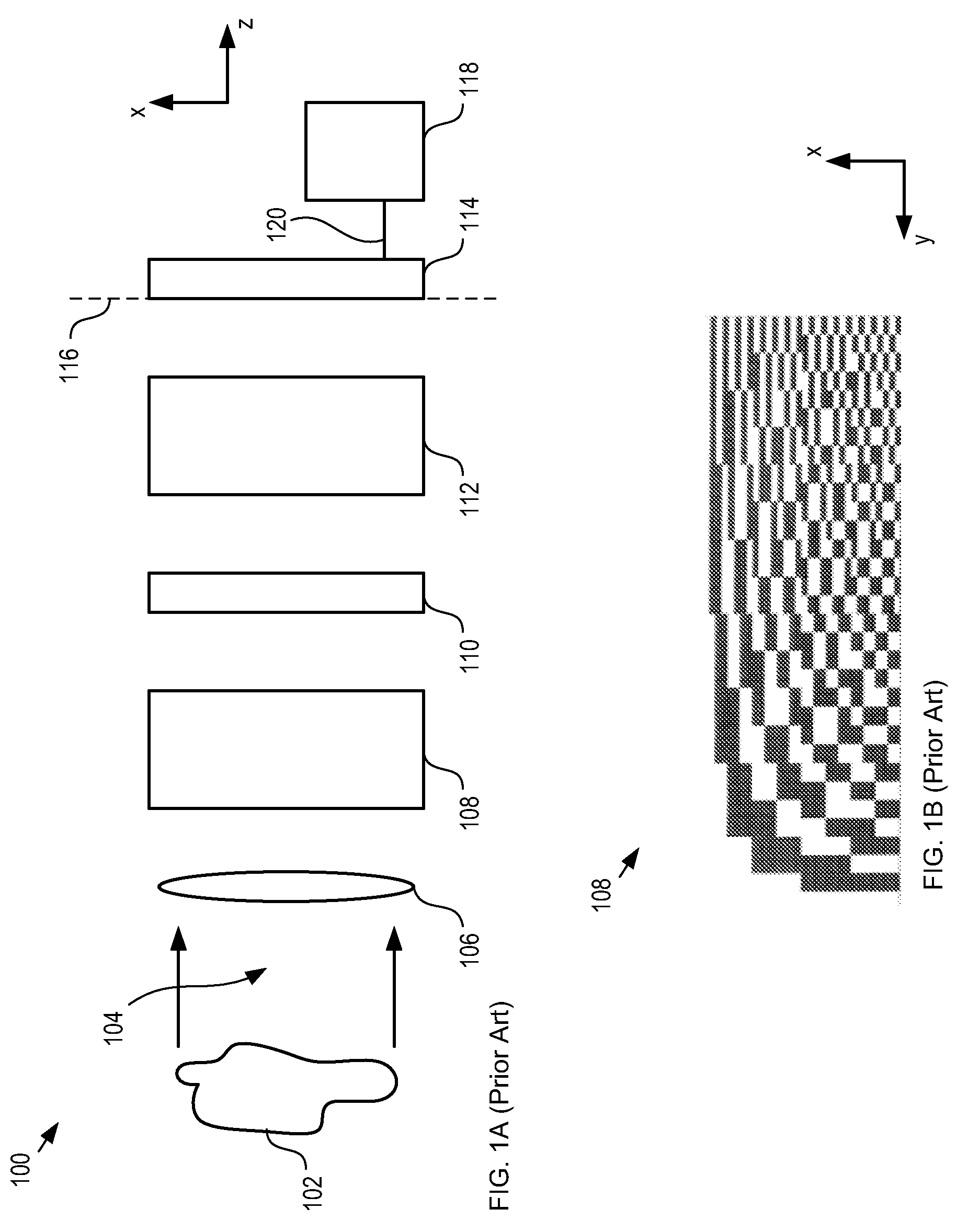
[0037]FIG. 1A depicts a schematic diagram of a portion of a snap-shot spectral imager in accordance with the prior art. Imager 100 comprises lens 106, disperser 108, coded aperture 110, d...


PUM


Abstract

The present invention enables snap-shot spectral imaging of a scene at high image generation rates. Light from the scene is processed through an optical system that comprises a coded-aperture. The optical system projects a plurality of images, each characterized by only one of a plurality of spectral components, onto a photodetector array. The plurality of images is interspersed on the photodetector array, but no photodetector receives light characterized by more than one of the plurality of spectral components. As a result, computation of the spatio-spectral datacube that describes the scene is simplified. The present invention, therefore, enables rapid spectral imaging of the scene.

Description

CROSS REFERENCE TO RELATED APPLICATIONS[0001]This case claims priority to U.S. Provisional Patent Application Ser. No. 61 / 167,335, filed Apr. 7, 2009, which is incorporated by reference.[0002]If there are any contradictions or inconsistencies in language between this application and one or more of the cases that have been incorporated by reference that might affect the interpretation of the claims in this case, the claims in this case should be interpreted to be consistent with the language in this case.FIELD OF THE INVENTION[0003]The present invention relates to imaging in general, and, more particularly, to spectral imaging.BACKGROUND OF THE INVENTION[0004]Spectral imaging is a technique for generating a spatial map of the wavelength variations of light from a scene. It has found use in many applications, such as environmental sensing, military and civilian surveillance, homeland security, military target discrimination, astrophysics, metrology, and biomedical imaging.[0005]The sp...

Claims


Application Information

Patent Timeline
Patent Type & Authority Patents(United States)
IPC IPC(8): G01J3/28
CPCG01J3/02G01J3/0208G01J3/0229G01J3/2803G01J3/2823
Inventor BRADY, DAVID JONESMCCAIN, SCOTT THOMASPORTNOY, ANDREW DAVID
Owner DUKE UNIV
Why Eureka
Try Eureka