Magnetic head and manufacturing method thereof

a technology of magnetic head and manufacturing method, which is applied in the field of magnetic read head, can solve the problems of increasing noise, increasing magnetization fluctuation noise proportional to output, and inability to improve the signal-to-noise ratio, etc., and achieves stable reading operation, less magnetic fluctuation noise, and increased volume of the entire free layer

Inactive Publication Date: 2012-04-03
WESTERN DIGITAL TECH INC
View PDF7 Cites 17 Cited by
  • Summary
  • Abstract
  • Description
  • Claims
  • Application Information

AI Technical Summary

Benefits of technology

[0006]Embodiments of the present invention provide a magnetic head having a read head of stable reading operation and with less magnetic fluctuation noise. According to the embodiment of FIG. 1, a free layer has a structure comprising two ferromagnetic layers (free layer 1, free layer 2) that are coupled anti-ferromagnetically by way of a non-magnetic intermediate layer 19, in which the magnetization amount of the free layer 1 (18) is set to larger than the magnetization amount of the free layer 2 (20). Further, the magnetic domains in the free layer 1 (18) and the free layer 2 (20) are stabilized simultaneously by increasing the distance Sp2 between the free layer 2 (20) and the magnetic domain control film 41 more than the distance Sp1 between the free layer 1 (18) and the magnetic domain control film 41, thereby adjusting the magnetization amount of the magnetic domain control film 41. Further, the volume of the entire free layer is increased thereby greatly decreasing the magnetic fluctuation noises, to obtain a read head 100 showing a high SN ratio.

Problems solved by technology

Then, a relative angle between the magnetization in the free layer and the magnetization in the pinned layer fluctuates greatly, resulting in increased noise.
Further, it has a characteristic that the magnetization fluctuation noise increases in proportion to the output.
This means that unless the magnetization fluctuation noise per se is suppressed, improvement for a signal-to-noise ratio cannot be expected even when the output is merely increased.

Method used


Image

  • Magnetic head and manufacturing method thereof
  • Magnetic head and manufacturing method thereof
  • Magnetic head and manufacturing method thereof

Examples


embodiment 1

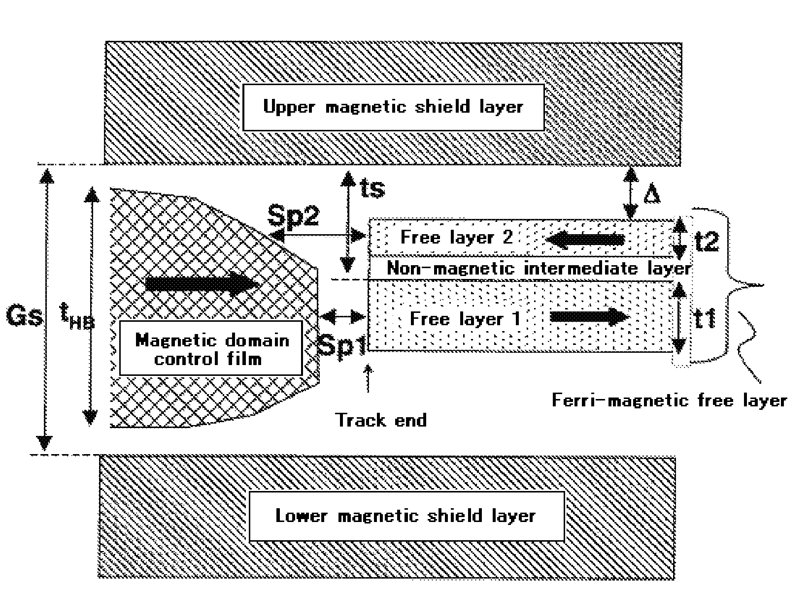
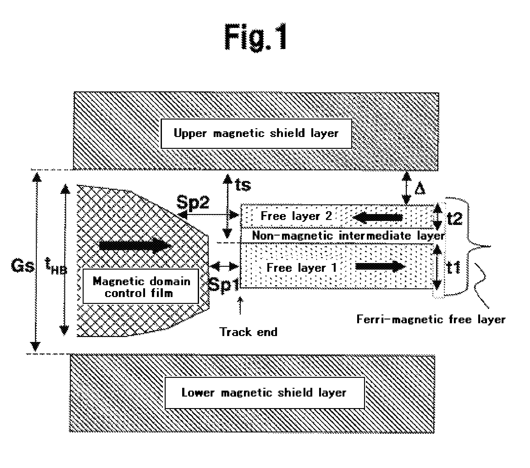
[0043]In Embodiment 1, a magnetic domain control film and a magnetoresistive film are formed so as to satisfy (Br·t)PM≧(9×Sp1 / ts)×{(Bs·t)1−(Bs·t)2} and Sp2>2×Sp1. As the magnetoresistive film, a current-perpendicular-to-plane TMR film was adopted. A permanent magnet was disposed as the magnetic domain control film to both ends in the direction of the track width of the magnetoresistive film.

[0044]FIG. 4 is an enlarged view of a read head according to Embodiment 1 at the surface opposing to a recording medium. A read head 100 has a lower magnetic shield layer 1 comprising NiFe or the like of 3 μm thickness disposed by way of base alumina on a substrate (not illustrated), a lower electrode layer 3 disposed on the lower magnetic shield layer 1, a TMR film 10 disposed above the lower electrode layer 3, a magnetic domain control film 41 disposed on both ends in the direction of the track width of the TMR film 10, an upper electrode layer 4 disposed above the TMR film 10 and above the mag...

embodiment 2

[0053]FIG. 8 shows a schematic perspective cross sectional view of a magnetic head according to Embodiment 2. A magnetic head 300 is a magnetic head for longitudinal magnetic recording and comprises the read head 100 of Embodiment 1 and a longitudinal magnetic write head 310 in combination. The longitudinal magnetic write head 310 has a lower core 50 disposed above the read head 100 by way of a non-magnetic separation layer 54 comprising alumina or the like of 500 nm thickness, an upper core 51, and a coil 52 for generating a magnetic flux disposed between the cores. A recording magnetic field is generated in a recording gap between the upper and lower cores 51, 50 by supplying a writing current in a desired pattern to the coil 52, which is applied in a desired pattern to a magnetic medium to write a magnetization information having a desired magnetizing direction to the magnetic medium. Further, information is read by detecting the magnetic field leaking from the magnetization info...


PUM

PropertyMeasurementUnit
thicknessaaaaaaaaaa
thicknessaaaaaaaaaa
thicknessaaaaaaaaaa

Abstract

Embodiments of the present invention provide a magnetic head having a read head of stable reading operation and with less magnetic fluctuation noise. According to one embodiment, a free layer has a structure comprising two ferromagnetic layers (a first free layer and a second free layer) that are coupled anti-ferromagnetically by way of a non-magnetic intermediate layer, in which the magnetization amount of the first free layer is set to larger than the magnetization amount of the second free layer. Further, the magnetic domains in the first free layer and the second free layer are stabilized simultaneously by increasing the distance between the second free layer and the magnetic domain control film to be more than the distance between the first free layer and the magnetic domain control film, thereby adjusting the magnetization amount of the magnetic domain control film. Further, the volume of the entire free layer is increased thereby greatly decreasing the magnetic fluctuation noises, to obtain a read head showing a high SN ratio.

Description

CROSS-REFERENCE TO RELATED APPLICATION[0001]The instant nonprovisional patent application claims priority to Japanese Patent Application No. 2008-108925 filed Apr. 18, 2008, and which is incorporated by reference in its entirety herein for all purposes.BACKGROUND OF THE INVENTION[0002]Generally a magnetic read head includes a pair of upper and lower magnetic shield layers, a magnetoresistive film disposed therebetween, and a pair of electrodes connected electrically to the magnetoresistive film. In the case of magnetic recording and reproducing apparatus having an areal recording density in excess of 300 Gbits per 1 square inch, a high sensitive read device such as a tunneling magnetoresistive film (TMR film) or a current-perpendicular-to-plane giant magnetoresistive film (CPP-GMR) is utilized as a magnetoresistive film. The magnetoresistive film has a free layer, an intermediate layer, and a pinned layer, in which the magnetization in the free layer rotates in accordance with the c...

Claims


Application Information

Patent Timeline
Patent Type & Authority Patents(United States)
IPC IPC(8): G11B5/39
CPCB82Y10/00B82Y25/00G11B5/3909G11B5/3912G11B5/3932G11B2005/3996
Inventor HATATANI, MASAHIKOWATANABE, KATSUROYOSHIDA, NUBUOHOSHINO, KATSUMI
Owner WESTERN DIGITAL TECH INC
Why Eureka
Try Eureka