
Self-cooled thyristor valve

a thyristor valve and self-cooling technology, applied in the field of thyristor valves, can solve the problems of shortening the service life of the switch, and affecting the operation of the switch

Inactive Publication Date: 2012-04-03
CHINA ELECTRIC POWER RES INST
View PDF8 Cites 11 Cited by
  • Summary
  • Abstract
  • Description
  • Claims
  • Application Information

AI Technical Summary

Benefits of technology

[0006]Preferred embodiments of the present invention seek to overcome the above disadvantages of the prior device and provide a compact, small, and reliable self-cooled thyristor valve.
[0016]This invention adopted six inches thyristor element, this provides lower thermal impedance and surge current resistance, which is on behalf of the update technology all over the world.
[0017]This thyristor valve ensures that it is reliable and the feasible to operating the press-fit mechanism because it is well-structured, convenient to install and needs little preload force, as well as the press-fit mechanism adopted two round contacting surfaces, it ensures its force balance and reliability of the thyristor string during and after been pressed tightly.
[0019]This invention adopts the well-structured damped resistor; this reduces the surface temperature of high dissipation power damped resistor, eliminates the heat element effect to other elements around it, and improves the global reliability of the thyristor.

Problems solved by technology

It leads some fault positions current exceed the interrupting capacity of the switches.
Generally, the switch is very dear, and renew a switch will take much time; therefore, people always adopt various technical measures to limit the fault current.
So the current will be limited.
But in normal condition, a set of complex and expensive cooling system are need due to the long period operation of the thyristor.
This reduces the reliability of the entire device.

Method used


Image

  • Self-cooled thyristor valve
  • Self-cooled thyristor valve
  • Self-cooled thyristor valve

Examples


Embodiment Construction

[0038]The detail of the embodiments is described as below incorporated with the figures by way of cross-reference.

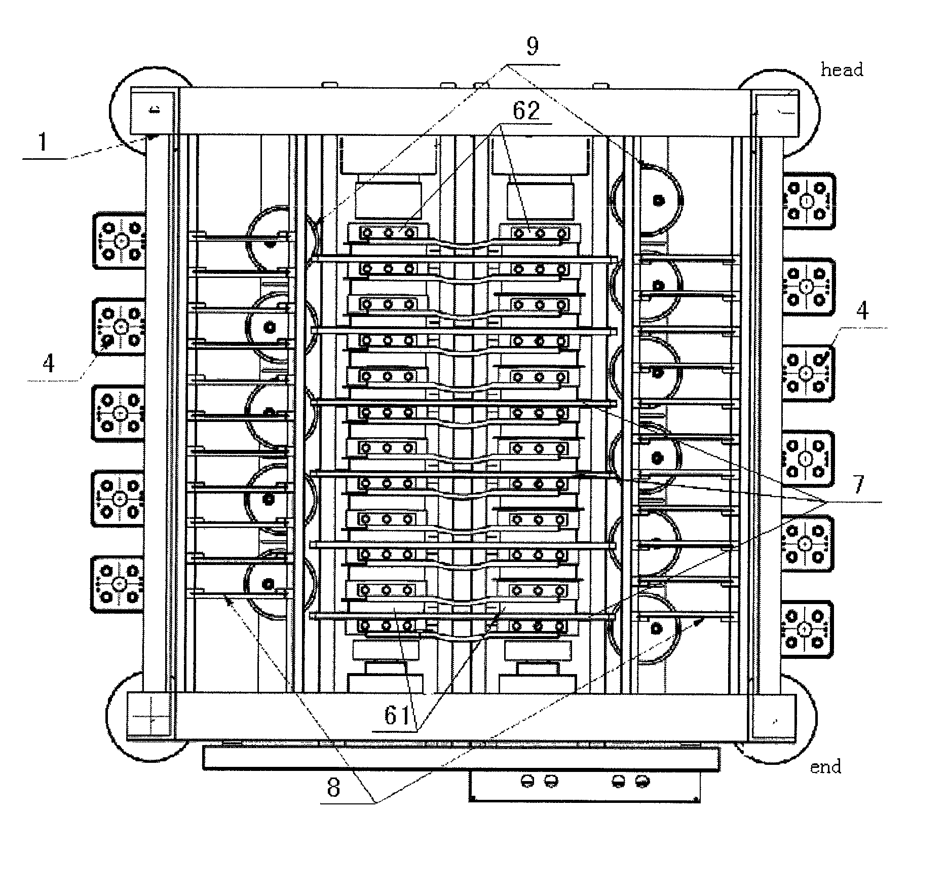
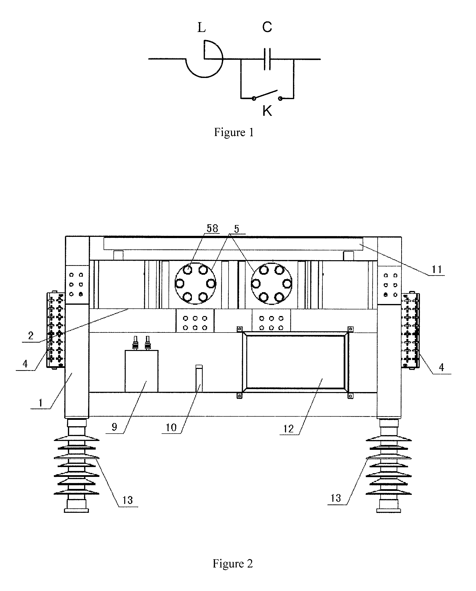
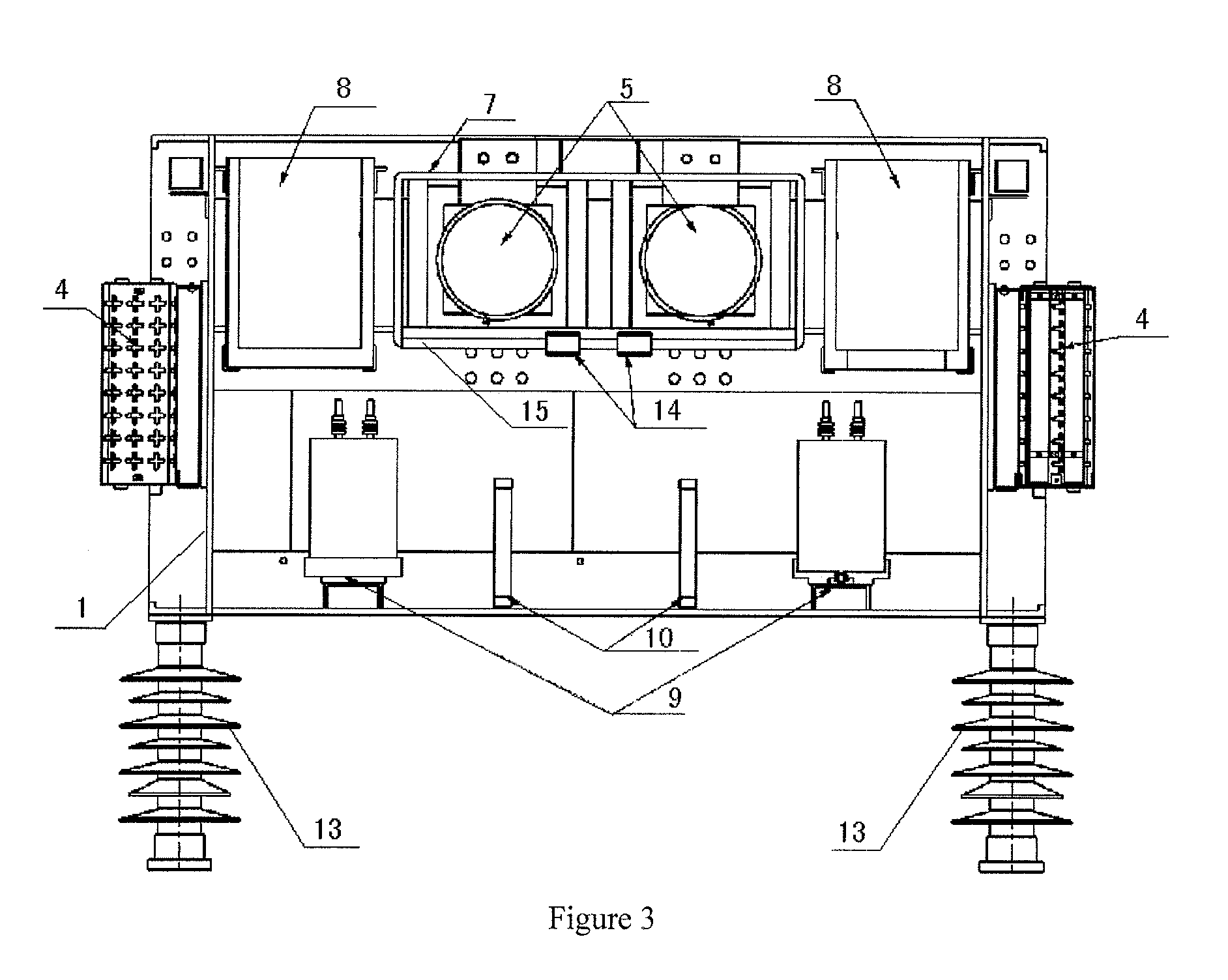
[0039]As FIGS. 2-6 shown, a self-cooled thyristor valve, it is horizontal structure consisted by frames 1, frames 1 is divided into top and below two spaces by a crossbeam 2, there are four insulators 13 at the bottom of the frames which is used for supporting the frames. The front and the back frames 1 are welded by triangle aluminum plates; this ensures the structural strength and reduces the weight of the frames.

[0040]There are two thyistor strings 6 in said frame top space, and both of them are installed on the crossbeam 2. Thyistor strings are compressed tightly at two extremities by press-fit mechanism 5. Each thyistor string contains eleven thyistors and twelve cooler, and they arranges interval. The two thyistor strings straightly cross six current transformer iron core 15 of the current transformer coil (CT coil). All of these current transformer coils 7 are arr...


PUM


Abstract

The present invention relates to a self-cooled thyistor device for ultra-high voltage fault current limiter. a self-cooled thyristor valve, it adopts horizontal structure consisted by frames, frames is divided into upper and below two spaces by crossbeams, the bottom of frames is supported by insulators. There is a cross plate between two vertical said frames, the cross plate mounts resistors connect with a high potential plate and capacitor through two wires. There is a thyistor string in said frame upper space, which is constituted of thyistors and cooler series. The thyistor string is compressed tightly by press-fit mechanism, thyistor string crosses current transformers. There are high potential plates on both sides of the thyistor, the number of the potential plates is equal to that of thyistor. One side of the high potential plates links frames, said current transformers connects with high potential plates. There are capacitors and resistors connected with the bottom plate of said frames in the below space. The small and well-structured invention meets the requirement of the energy on continuous trigger condition, improves the global reliability of thyristor valve.

Description

UNITED STATED PATENT APPLICATION FOR RELATED APPLICATIONS[0001]This Application is a United States National Stage Application filed under 35 U.S.C. §371 of PCT Patent Application Serial No. PCT / CN2009 / 001509 filed on Dec. 18, 2009, which claims the benefit of Chinese Patent Application Serial No. 200810247467.0 filed on Dec. 31, 2008, the disclosures of all of which are hereby incorporated by reference in their entirety.FIELD OF THE INVENTION[0002]The present invention relates to a thyristor valve, and relates particularly to a self-cooled thyristor valve used for ultra-high voltage fault current limiter.BACKGROUND OF THE INVENTION[0003]With the development of power systems, novel powers have been increasing into the systems or the subnets connect with each other. This increases the capacity of short circuit of systems. It leads some fault positions current exceed the interrupting capacity of the switches. Generally, the switch is very dear, and renew a switch will take much time; t...

Claims


Application Information

Patent Timeline
Patent Type & Authority Patents(United States)
IPC IPC(8): H05K7/20
CPCH01L25/00H01L23/34H01L23/48H01L2924/0002H01L2924/00
Inventor TANG, GUANGFULAN, YUANLIANGWANG, HUAFENGLUAN, HONGZHOULI, ZHIQIYU, HAIYUWANG, HUAXINZHANG, JING
Owner CHINA ELECTRIC POWER RES INST
Learn More