Condenser microphone

a condenser microphone and microphone technology, applied in piezoelectric/electrostrictive transducers, coupling device connections, microphone structural associations, etc., can solve the problems of incomplete function, inability to fully protect the flexible pipe portion, and the microphone cable is vulnerable to noise (electromagnetic waves) coming, etc., to achieve high productivity

Active Publication Date: 2012-04-03
AUDIO-TECHNICA
View PDF3 Cites 4 Cited by
  • Summary
  • Abstract
  • Description
  • Claims
  • Application Information

AI Technical Summary

Benefits of technology

[0017]According to this mode, since the microphone cable is inserted through the support pipe in the state in which the shield covered wire having no skin is exposed throughout the entire length thereof, and is provided with the conductive contact, in which the central part thereof is held in a state of conducting with the shield covered wire, and the wing pieces on both sides are extended in the direction substantially perpendicular to the axis line of the microphone cable so as to be in contact elastically with the inner surface of the support pipe, in the predetermined portion of the shield covered wire, the movement of the microphone cable in the support pipe is restricted while the shield covered wire of the microphone cable is brought into contact with the inner surface of the support pipe at many points. Therefore, the shielding function against electromagnetic waves is improved significantly, and also the generation of noise caused by looseness contact of the shield covered wire with the inner wall of the support pipe can be prevented.
[0045]According to this mode, in the method for manufacturing a condenser microphone, in the case where the support pipe includes a nonflexible metallic pipe, the expandable ink material is applied to the shield covered wire in the portion corresponding to the metallic pipe at a predetermined interval, so that the condenser microphone in which noise is not generated especially in the metallic pipe portion can be manufactured with high productivity.

Problems solved by technology

The microphone cable is vulnerable to noise (electromagnetic waves) coming from the outside because the sound signals are transmitted unbalancedly.
The flexible pipe functions as a shield for the microphone cable, but this function is not complete.
However, when viewed as the entire of microphone, the shield in the portion of the flexible pipe is incomplete.
Therefore, strong electromagnetic waves intrude into the microphone through the flexible pipe, and resultantly noise may be generated as described above.
However, problems to be solved still remain.
In this case, if the whole of the support pipe is formed by the flexible pipe, it bends excessively, so that the appearance is bad.
This noise may also be generated in the case where the microphone cable moves and the shield covered wire comes into contact with the inner wall of the flexible pipe when the flexible pipe is bent, for example, in the state in which the support pipe is made straight, and the shield covered wire of the microphone cable is not in contact with the inner wall of the flexible pipe.

Method used


Image

  • Condenser microphone
  • Condenser microphone
  • Condenser microphone

Examples


first embodiment

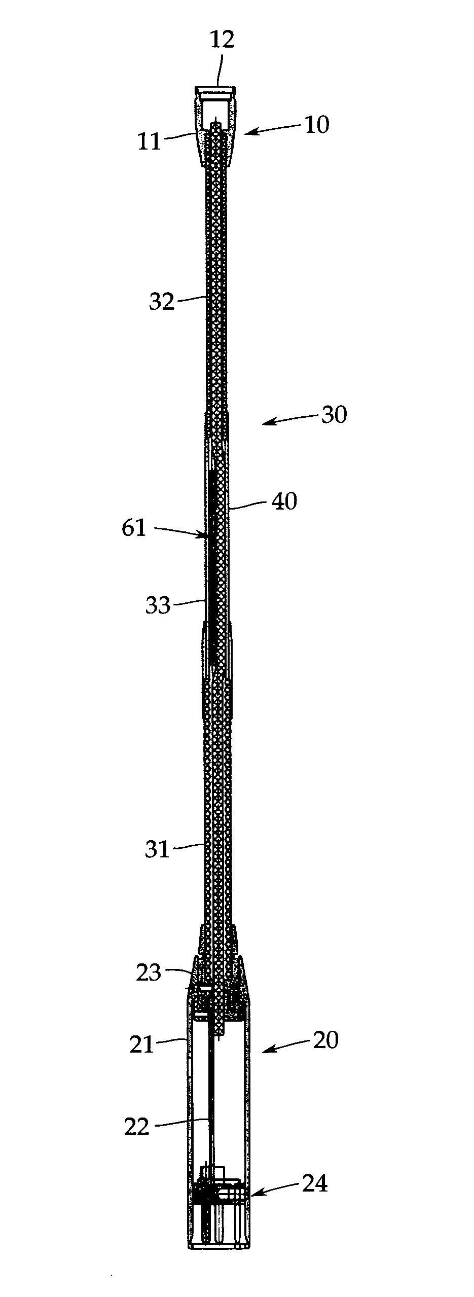
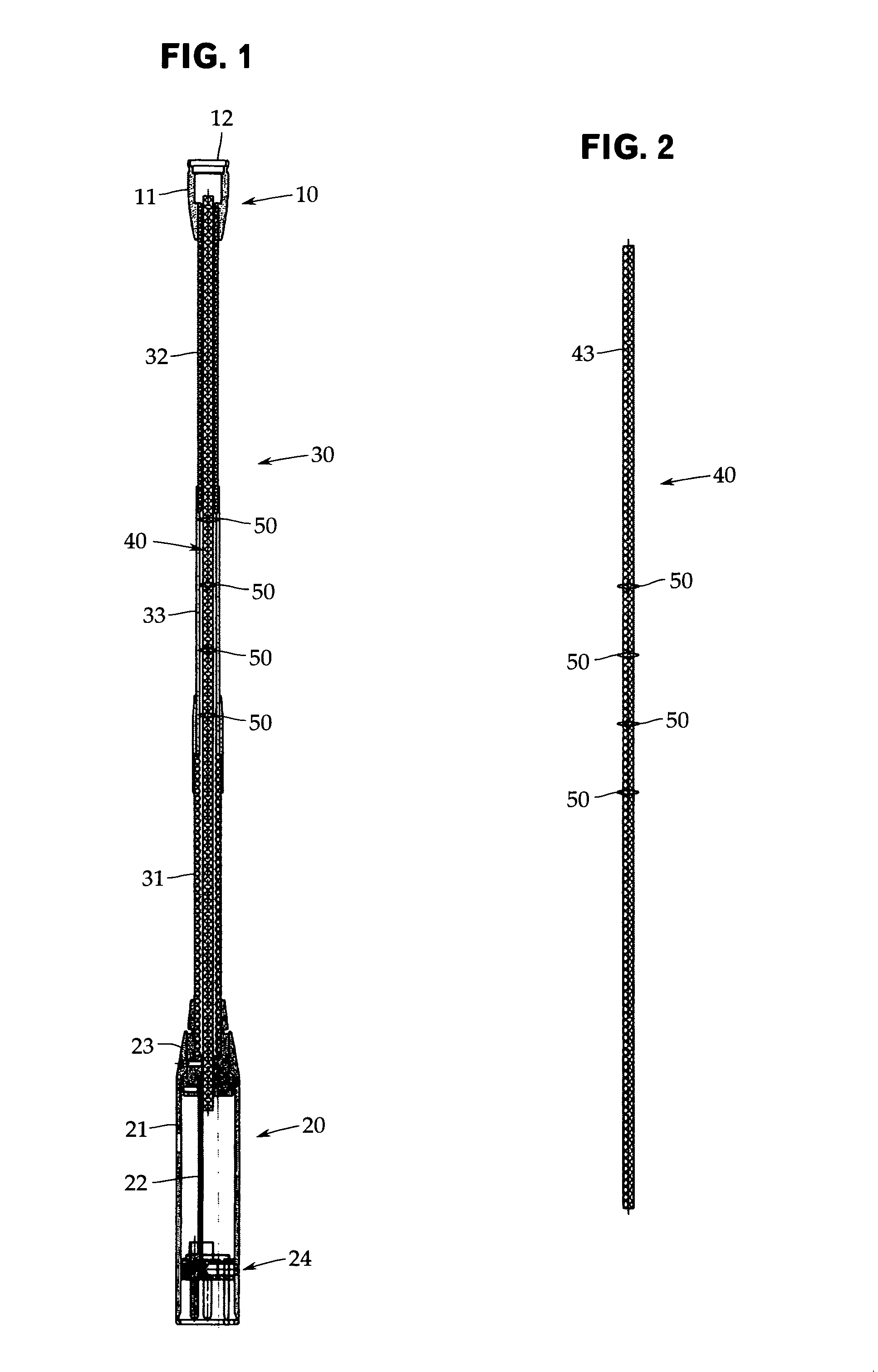
[0061]As shown in FIG. 1, a condenser microphone in accordance with the first embodiment includes, as a basic configuration, a condenser microphone unit 10, an output module section (power module section) 20, and a support pipe 30 that supports the condenser microphone unit 10.

[0062]The condenser microphone unit 10 has a cylindrical shield case 11 formed of, for example, a brass material, and a microphone capsule 12 is mounted in the tip end part of the shield case 11.

[0063]Although not shown in the figures, in the microphone capsule 12, an electrostatic acoustoelectric converter consisting of a diaphragm and a backplate arranged opposedly via a spacer ring is included. As a polarization material, an electret may be used. Although not shown in the figures similarly, in the shield case 11, a field effect transistor (FET) serving as an impedance converter connected electrically to the backplate is housed.

[0064]The output module section 20 has a cylindrical shield case 21 that is also ...

second embodiment

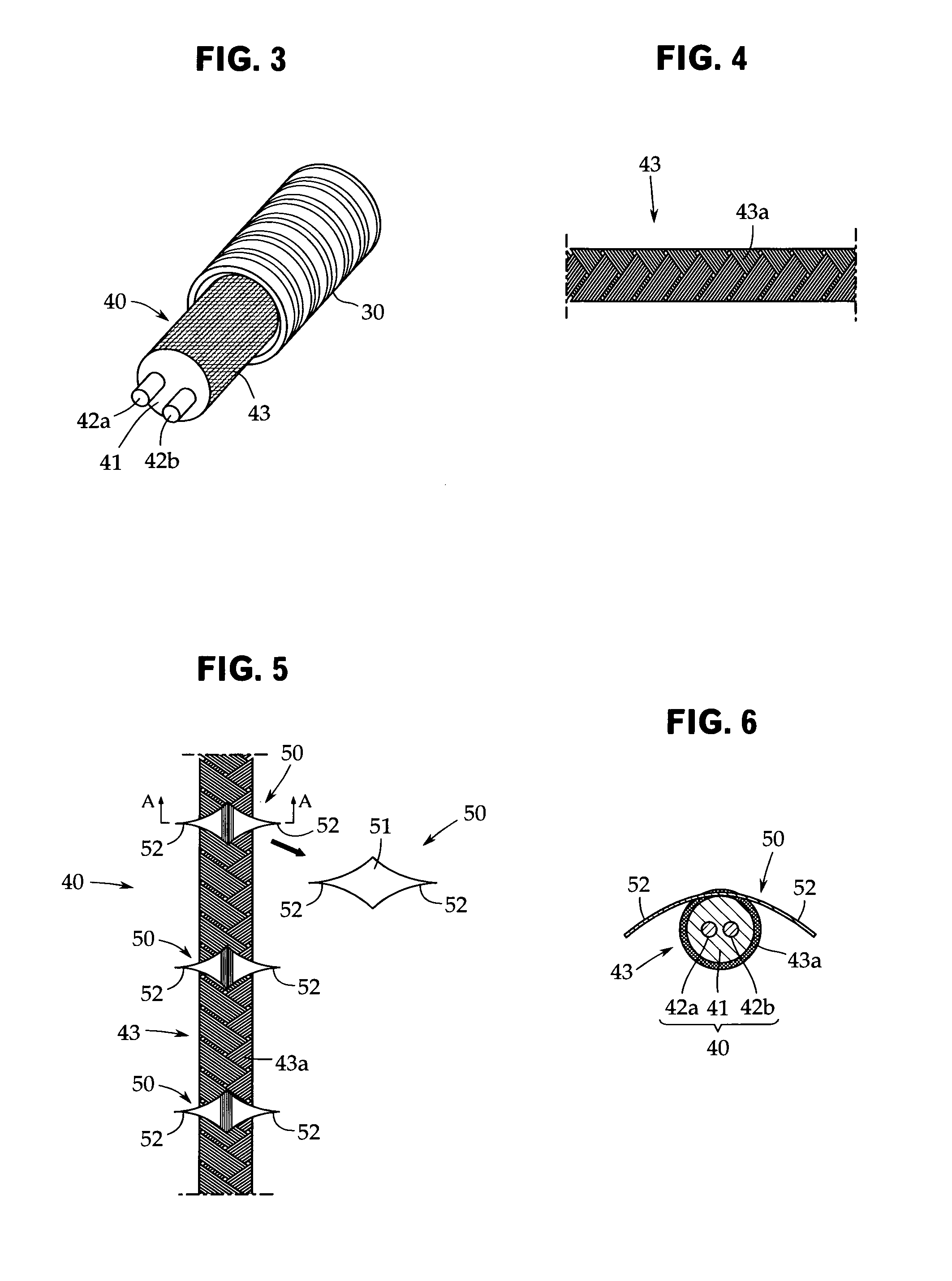
[0085]In the second embodiment as well, as shown in FIGS. 8 and 9, the microphone cable 40 is inserted through the support pipe 30 in the state in which the external sheath is removed throughout the entire length thereof and the shield covered wire 43 is exposed. To prevent the generation of noise caused by looseness contact by restricting the movement of the microphone cable 40 in the support pipe 30, a braid 61 is used as an elastic linear body 60 that is formed by plantingly providing fibers in the radial direction around a core wire and has elasticity in the radial direction due to the fibers.

[0086]The braid 61 is a string formed by plantingly providing fibers 63, which are formed of, for example, nylon, in the radial direction around the wire 62, which is the core wire, by holding the fibers 63 between the wires 62 and twisting them, and has elasticity in the radial direction because the fibers 63 are fluffy. This braid may be a commercially available braid that is used, for ex...

third embodiment

[0095]In the third embodiment, as shown in FIG. 11, the braid yarn 64 is inserted through the support pipe 30 together with the microphone cable 40 as shown in FIG. 10 in a state of being provided throughout the entire length of the exposed shield covered wire 43 of the microphone cable 40.

[0096]According to this configuration, as in the second embodiment, the microphone cable 40 is pushed against the inner surface of the support pipe 30 by the elasticity in the radial direction due to the fluffy fibers of the braid yarn 64, so that the movement of the microphone cable 40 is restricted, and thus the generation of noise caused by looseness contact can be prevented effectively. To increase the shielding function, it is preferable that the fibers of the braid yarn 64 be made conductive fibers.

[0097]Next, a fourth embodiment of the present invention is explained by reference to FIGS. 12 and 13. FIG. 12 is a sectional view of a gooseneck condenser microphone in accordance with the fourth...


PUM

PropertyMeasurementUnit
resistanceaaaaaaaaaa
flexibleaaaaaaaaaa
lengthaaaaaaaaaa

Abstract

In a gooseneck condenser microphone that supports a condenser microphone unit via a support pipe, when the microphone is used by inserting a microphone cable through the support pipe in the state in which a shield covered wire having no skin is exposed throughout the entire length thereof, the movement of the microphone cable in the support pipe is restricted, by which the generation of noise caused by looseness contact of the shield covered wire with the inner wall of the support pipe is prevented. The microphone cable 40 is inserted through the support pipe in the state in which the shield covered wire 43 having no skin is exposed throughout the entire length thereof, and is provided with a conductive contact, in which the central part 51 thereof is held in a state of conducting with the shield covered wire 43, and wing pieces 52 on both sides are extended in the direction substantially perpendicular to the axis line of the microphone cable 40 so as to be in contact elastically with the inner surface of the support pipe, in the predetermined portion of the shield covered wire 43.

Description

TECHNICAL FIELD[0001]The present invention relates to a gooseneck condenser microphone that supports a condenser microphone unit via a support pipe including a flexible pipe, and a method for manufacturing the gooseneck condenser microphone. More particularly, it relates to a technique for preventing the generation of noise caused by high-frequency electromagnetic wave noise generated from a cellular phone etc.BACKGROUND ART[0002]As described in, for example, Patent Document 1 (Japanese Patent Application Publication No. H11-341576), a gooseneck condenser microphone is preferably used in conference facilities such as international conference rooms from the viewpoint of its simple appearance and ease of adjustment of the angle and height of the microphone.[0003]In the gooseneck condenser microphone, a condenser microphone unit and an output module section are formed separately. The condenser microphone unit is supported on the output module section via a support pipe including a flex...

Claims


Application Information

Patent Timeline
Patent Type & Authority Patents(United States)
IPC IPC(8): H04R9/08
CPCH04R1/04Y10T29/49005H04R1/06
Inventor AKINO, HIROSHIMATSUI, NORIKO
Owner AUDIO-TECHNICA
Why Eureka
Try Eureka