
Methods for heat exchanger network energy efficiency assessment and lifetime retrofit

a heat exchanger network and energy efficiency assessment technology, applied in the field of energy recovery systems, can solve the problems of nlp) not leading to the best, incomplete different network structure retrofit solution,

Active Publication Date: 2012-04-03
SAUDI ARABIAN OIL CO
View PDF27 Cites 13 Cited by
  • Summary
  • Abstract
  • Description
  • Claims
  • Application Information

AI Technical Summary

Benefits of technology

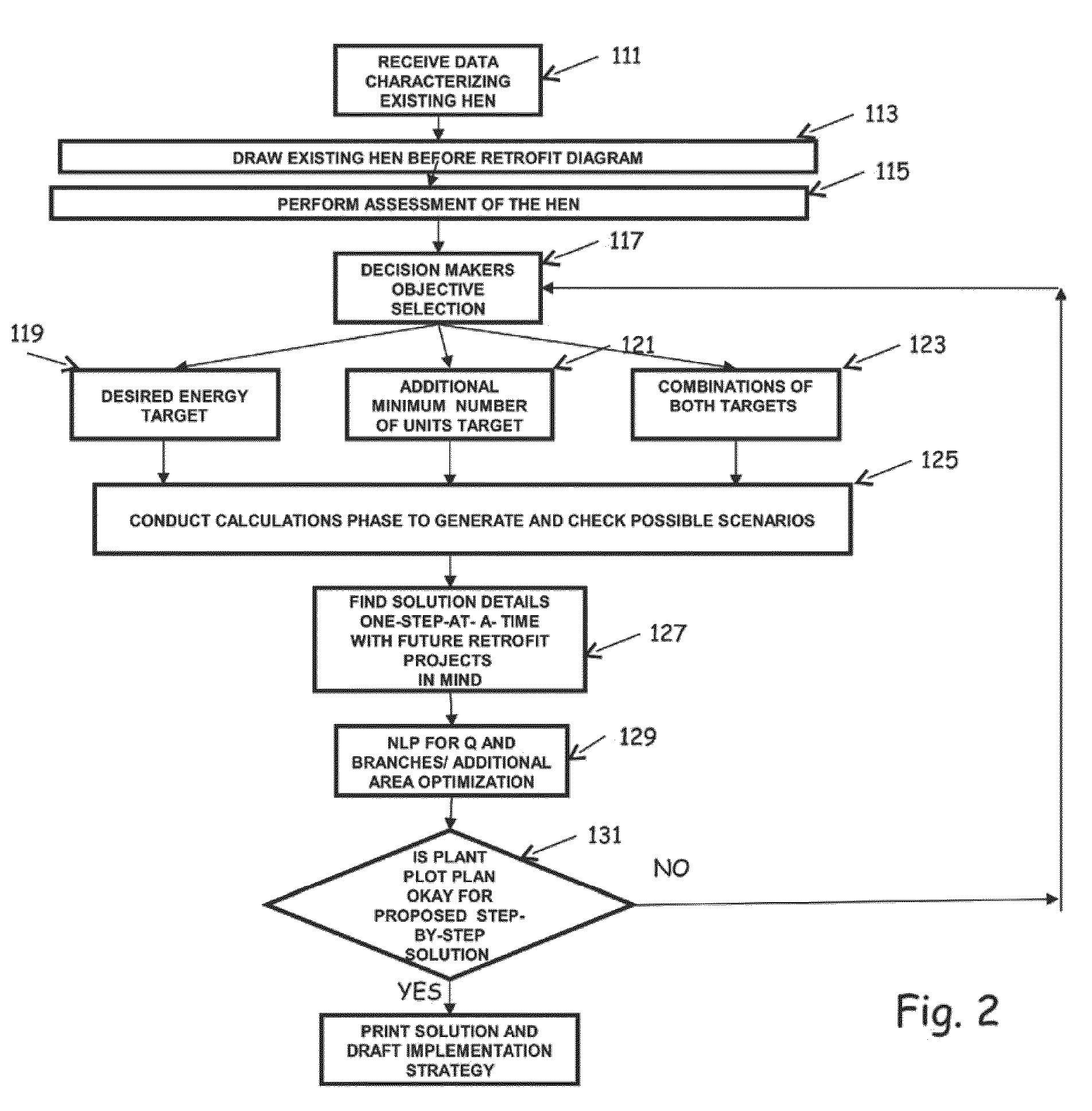
[0029]In view of the foregoing, various embodiments of the present invention advantageously include systems, program product, and methods for managing heat exchanger network energy efficiency and retrofits for an industrial facility, which can rigorously assess the existing network, rigorously target for the solution before the go ahead of the retrofit project for practically attainable waste energy (heat and / or work) recovery and / or minimum number of units that need to be added to reach desired energy consumption targets or part of it, and to systematically render solutions that can be implemented in phases with a guarantee that the solution implemented today (in phase one) will not become an obstacle, or need to be demolished, for a tomorrow retrofit solution to be implemented at later time in the future in phases two, three and so on. Various embodiments of the present invention also include systems, program product, and methods which employ process steps whereby if the pinch point for a retrofit project changes its location due to the current and future network retrofit project solutions, including process parametric and structural modifications, such situation would not detrimentally affect the network's topology.
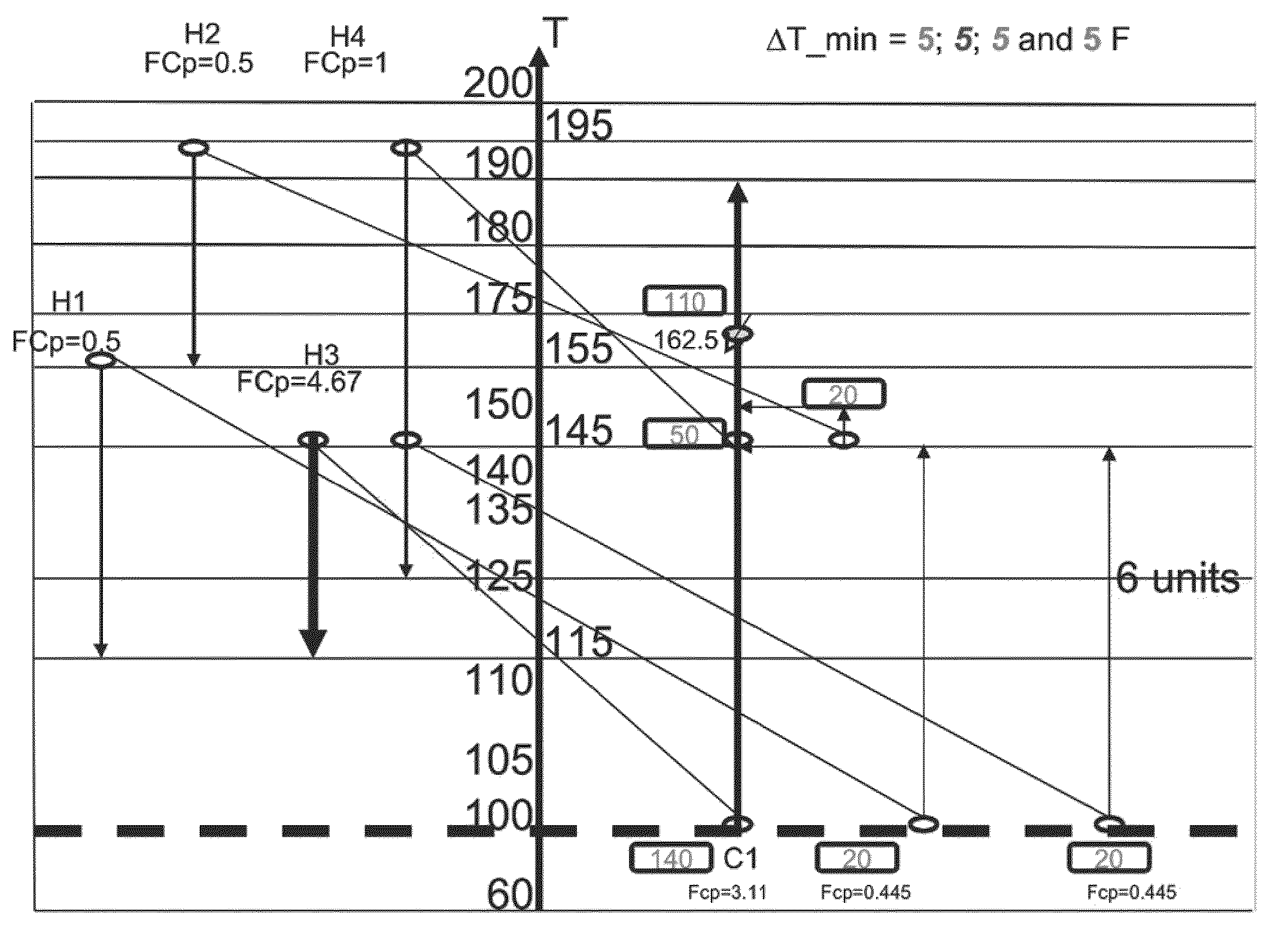
[0032]According to an embodiment of the present invention, the steps can also include graphically displaying the current heat transfer structure of the existing heat exchanger network. The graphical display can include a pinch point location temperature line identifying the pinch point for the heat exchanger network and one or more connection lines indicating heat transfer between a corresponding one or more hot process streams and one or more cold process streams above, below, and across the pinch point location line to provide ready identification of each heat exchanger in the heat exchanger network exchanging heat properly and / or improperly across the pinch point temperature. Each of the one or more connection lines can provide a linear graphical illustration of heat exchange across the pinch point location temperature line, extending between a respective hot process stream-cold process stream combination to enhance visual identification of such condition. The unique graphical representation can also enhance visual identification of process streams that primarily control pinch point location, the discrete pinch point locations, and the range of values for the pinch point locations, among others.
[0039]According to an exemplary configuration, the steps can also include identifying one or more of the plurality of process streams that control one or more pinch point location moves associated with a current heat exchanger network design that satisfies a desired increase in waste heat / energy recovery prior to constructing a corresponding prospective heat exchanger network design that satisfies the desired waste heat / energy recovery, and identifying each of one or more streams specific turning point temperatures associated with the one or more pinch point location moves. These features can be particularly advantageous, as they provide the designer the ability to locate an optimal pinch point location with future retrofit in mind prior to expending significant resources in the design process, and to identify process conditions and / or characteristics to achieve the optimal pinch point location.
[0047]Various embodiments of the present invention advantageously exhibit several folds of uniqueness, such as, for example, in the methodology of representing the existing HEN, in the methodology of testing and analyzing the existing HEN from “energy-efficiency” point of view, in the energy consumption and number of units targeting phase, and finally in the systematic finding of the retrofit solutions, which is evolutionary in implementation but revolutionary in thinking as it serves the novel concept of plant lifetime retrofit-ability without contradiction between past and future retrofits and without losing the opportunities of continuing more retrofit projects due to either physical impracticality (inability to make the desired structural modifications) or economic impracticality (the situation in which more desirable retrofit actions became too expensive to be justified). Various embodiments of the present invention also advantageously address the retrofit of both single and multiple-utilities HEN for waste energy quality recovery, and can employ all possible combinations of process changes that not only include the HEN, but also the rest of the plant design and operating conditions, for finding the best heat exchanger networks retrofit solutions.
[0049]As noted previously, in the current pinch-based methods (process and network), the pinch point location will be changing upon performing modifications. Hence, sequential modifications will likely become conflicting and lead to mediocre solution. Accordingly, embodiments of the present invention provide solutions which use interval inclusion methods for all possible pinch points. Various embodiments of the present invention advantageously also facilitate the identification of the hot stream(s) and / or the cold stream(s) that controls the pinch point location. Knowing such stream(s) ahead of deciding any modification can be considered a priori for any successful modification in both process conditions and HEN topology. The locating of the problem process pinch map is also useful to complete the picture of the process pinch interval especially when there is no process pinch as in threshold applications and we have only utility pinch(s) and in cases like CDU in which there are non-process-pinch points. The stream(s) having highest impact on energy recovery upon reducing its ΔT_min_i can be located and / or re-located on utility path(s), via re-matching.

Problems solved by technology

Using a different starting point, however, will likely result in a completely different network structure retrofit solution.
As such, if one starts with the wrong ΔT_min, the wrong structure will be obtained, and evolutionary heuristics and optimization techniques (NLP) will not lead to the best results since radical moves / changes from one structure to another are not feasible or possible.
That is, if the designer cannot accept the entire solution structure for one reason or another (e.g., capital needed and / or time for implementation, affect on other process units, etc.) the package will have to be rejected.
This can be troublesome as the targets defined for area and investment costs are not rigorous and very crude.
The use of pinch technology rules to find topological modifications in the existing HENs to overcome the so called network pinch, however, is not rigorous since it is based upon the assumption that the network pinch and the process pinch are not going to change its location due to the taken topological modification.
As the assumption is not correct, topological modifications can have counter effects on each other to the extent that they may completely negate the possibility of doing future retrofit projects.
That is, it may become impossible to employ a certain retrofit project due its counter effect on the previous projects, and so on, making the retrofit projects in sustainable.
For example, if the current HEN retrofit process is conducted using pinch technology concept including the evolutionary network pinch method, and then if in at least one time at any future network retrofit process a different pinch point location arises, e.g., due to process parametric and / or structural modifications, and if the different pinch point location indicates a need for a lesser minimum number of units than the one used in previous HEN retrofit project, the result may be a wasting of some of the HE units already added in the previous HEN retrofit.
Such use, however, is crude, based upon heuristics, and is not rigorous (repeatably accurate).
Although, as noted previously, most commercial software are currently using mathematical programming techniques to complement other methodologies, pure mathematical programming techniques have been less well received, particularly in the industry community.
For example, in the most widely used pinch technology method and its modifications, the method is non-systematic and involves heuristics that produce solutions whose quality depends entirely on the designer experience in applying such heuristics—i.e., the global ΔT_min should be used in determining the location of the pinch for an assumed best global ΔT_min.
Accordingly, the inventor has recognized that such methodology is not systematic, requiring iteration, and that pinch method initialization using an assumed best global ΔT_min is ad hoc, and thus, such methodology could not be used as a standard method for plant-lifetime retrofit.
Accordingly, such methodology could also not be used as a standard method for plant-lifetime retrofit.
The mathematical programming-based methods also have significant disadvantages.
For example, the mathematical programming-based methods provide little or almost no scope for user interaction.
Although it is currently possible to solve larger problems than before utilizing such methods, the current capacity is still not to the scale needed in many industrial applications.
As such, the inventor has recognized that including all possible process design modifications, different types and configurations of HE units and so on in the superstructure is impractical and will make the problem harder, intractable and impossible to solve.
The required information / data, however, is normally not available during the conceptual phase of the retrofit project, especially in a typical de-centralized engineering environment where projects cost control depends entirely on rigorous cost calculations, which typically, if not always, are made after the retrofit project basic engineering, and which are carried out at different departments, at least in most of the companies.
Further, it would be neither practical nor logical to assume with high fidelity all possible retrofit solutions that could potentially be implemented for a given plot plan of a facility or to rigorously develop cost correlations to each before running the mathematical program—especially when there is always more than one option to carry out a designated retrofit modification.
As such, the inventor has recognized that mathematical programming techniques will often lead to designs which include heat exchange across the pinch, which would be almost impossible to correct in future retrofits to recover extra heat.

Method used


Image

  • Methods for heat exchanger network energy efficiency assessment and lifetime retrofit
  • Methods for heat exchanger network energy efficiency assessment and lifetime retrofit
  • Methods for heat exchanger network energy efficiency assessment and lifetime retrofit

Examples


Embodiment Construction

[0085]The present invention will now be described more fully hereinafter with reference to the accompanying drawings, which illustrate embodiments of the invention. This invention may, however, be embodied in many different forms and should not be construed as limited to the illustrated embodiments set forth herein. Rather, these embodiments are provided so that this disclosure will be thorough and complete, and will fully convey the scope of the invention to those skilled in the art. Like numbers refer to like elements throughout. Prime notation, if used, indicates similar elements in alternative embodiments.

[0086]Many different types of processes consume multiple steam levels and electricity to obtain an output result, or to produce a required product or compound. With large scale processes which consume significant amounts of steam for instance, it is preferable to optimize the steam and power system where possible. Heat exchanger network retrofit for waste energy recovery under ...


PUM


Abstract

Methods for managing / assessing heat exchanger network energy efficiency and retrofit for an industrial facility, are provided. An embodiment of a method can include the performance of perform various steps / operations including those for determining an optimal heat exchanger network retrofit projects sequence extending between a current heat exchanger network retrofit project satisfying a current desired waste energy recovery goal and a future heat exchanger network retrofit project satisfying the final waste energy recovery goal. The heat exchanger network retrofit projects sequence can be configured so that each subsequent project within the heat exchanger network retrofit projects sequence does not contradict any of the previous projects within the heat exchanger network retrofit projects sequence.

Description

RELATED APPLICATIONS[0001]This patent application is a continuation-in-part of U.S. patent application Ser. No. 12 / 898,475, filed Oct. 5, 2010, titled “Systems, Program Product, and Methods For Synthesizing Heat Exchanger Networks That Account For Future Higher Levels of Disturbances and Uncertainty and Identifying Optimal Topology For Future Retrofit,” which claims priority to the benefit of U.S. Provisional Patent Application No. 61 / 356,900, filed Jun. 21, 2010, titled “Systematic Synthesis Method and Program Product For Heat Exchanger Network Life-Cycle Switchability and Flexibility Under All Possible Combinations of Process Variations” and U.S. Provisional Application No. 61 / 256,754, filed Oct. 30, 2009, titled “System, Method, and Program Product for Synthesizing Non-Constrained and Constrained Heat Exchanger Networks and Identifying Optimal Topoloy for Future Retrofit,” and which is a continuation-in-part of U.S. patent application Ser. No. 12 / 715,255, filed Mar. 1, 2010, titl...

Claims


Application Information

Patent Timeline
Patent Type & Authority Patents(United States)
IPC IPC(8): G06F19/00
CPCF01K13/02G05B13/021G05B15/02G06Q10/06312G06F17/5009G06F30/20Y02P80/10
Inventor NOURELDIN, MAHMOUD BAHY
Owner SAUDI ARABIAN OIL CO
Learn More