
Modular network-assisted policy resolution

a technology of policy resolution and module network, applied in the field of multi-access policy resolution, can solve the problems of complex policies involved in this task, resolution delays, deep parallel sets of conditionals, etc., and achieve the effects of reducing the consumption of terminal resources, looping and oscillation, and reducing the delay of resolution

Inactive Publication Date: 2012-04-03
NOKIA TECH OY
View PDF6 Cites 9 Cited by
  • Summary
  • Abstract
  • Description
  • Claims
  • Application Information

AI Technical Summary

Benefits of technology

[0013]It is therefore an object of the present invention to provide an improved policy resolution scheme by means of which resolution delays, looping and oscillation as well as consumption of terminal resources can be reduced.
[0021]Accordingly, policy resolution is divided into clearly separate stages that handle specific types of trigger events and perform specific types of policy actions. Each policy resolution round goes through the stages in a chronological order. The set of trigger events is frozen before each round so that if there are trigger events that started after the round started, they will be postponed to the next resolution round. This avoids complex (nested) policy rules and reduces resolution delays, looping and oscillation in terminal connectivity when there are conflicting policies or events. Jitter or looping of resolution results or processes thus can be avoided. Certain types of triggers can be processed as an aggregate without dependence (except by scheduling based on the type of the aggregate) on other triggers. All factors affecting a certain trigger type are processed at the same time, and this allows for avoidance of unexpected consequences.

Problems solved by technology

The policies involved in this task easily become very complicated, and multiple trigger events can be received during very short periods of time.
This may lead to resolution delays, e.g. when the resolution engine first receives a trigger event telling it that a new flow has been initiated and selects a suitable network for it; and immediately afterwards receives a trigger event telling that the network has become unavailable, meaning that the resolution engine needs to select a new network.
Thus, adding more triggers leads to very deep parallel sets of conditionals, and excessively large policy descriptions.
Also, if a linearly executed policy uses only some part of all possible triggers, it is possible that the result causes another trigger event, whose separate linearly executed policy then results in triggers to the first policy.
Such looping could be e.g. activation of an interface triggered by a new traffic flow, where that activation could in a second policy result in blocking the use of another interface required for maintaining the traffic flow, which would then nullify reverse the outcome of the first policy.
However, the terminal may not be able to operate in an optimized way due to insufficient information on local access networks, such as lack of definitions for some access points or inability to detect nearby but yet just out of coverage radio networks.

Method used


Image

  • Modular network-assisted policy resolution
  • Modular network-assisted policy resolution
  • Modular network-assisted policy resolution

Examples


first embodiment

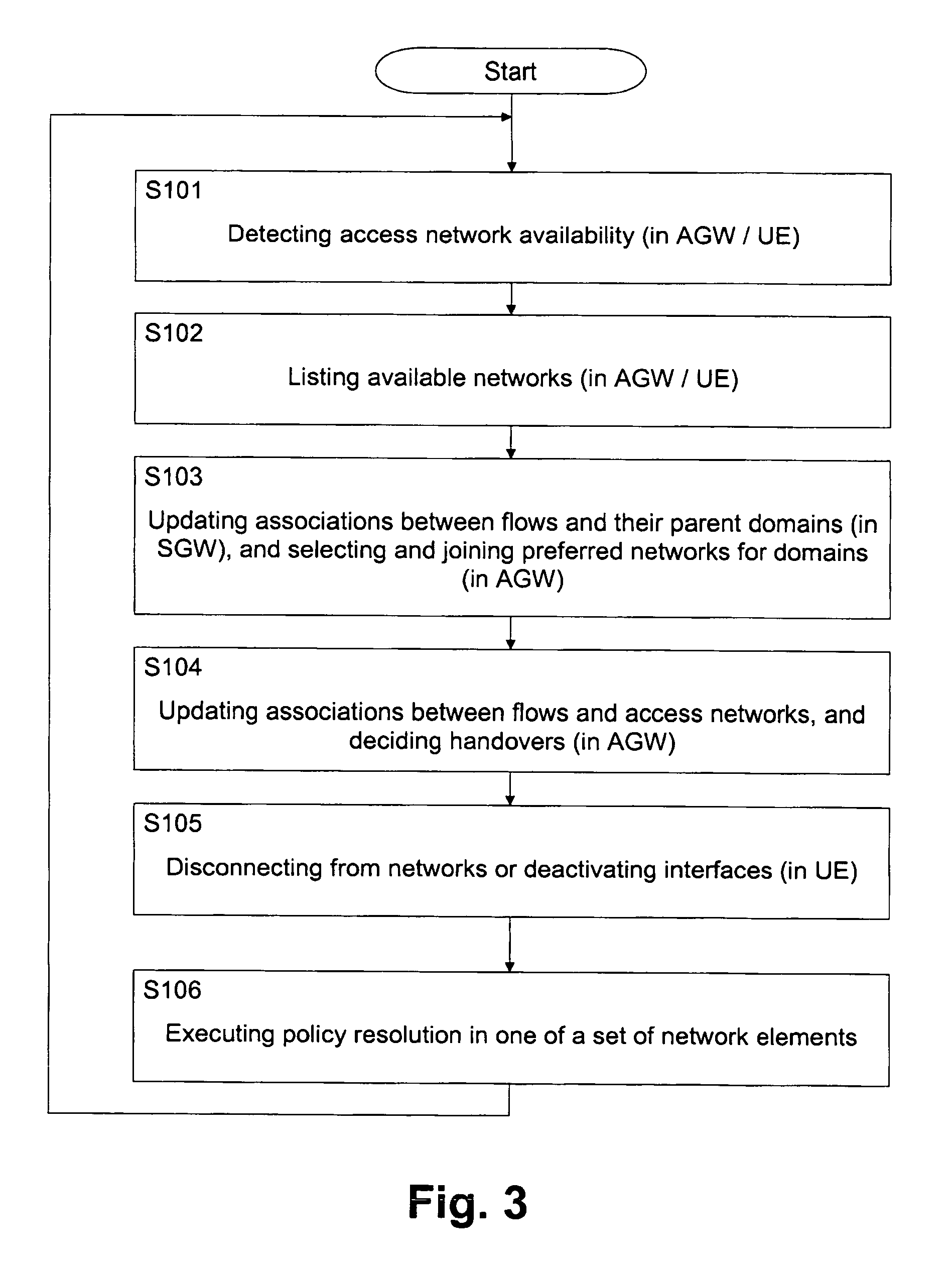
[0056] multi-access policy resolution is divided into clearly separate stages that handle specific types of trigger events and perform specific types of policy actions, while each policy resolution round goes through the stages in a chronological order.

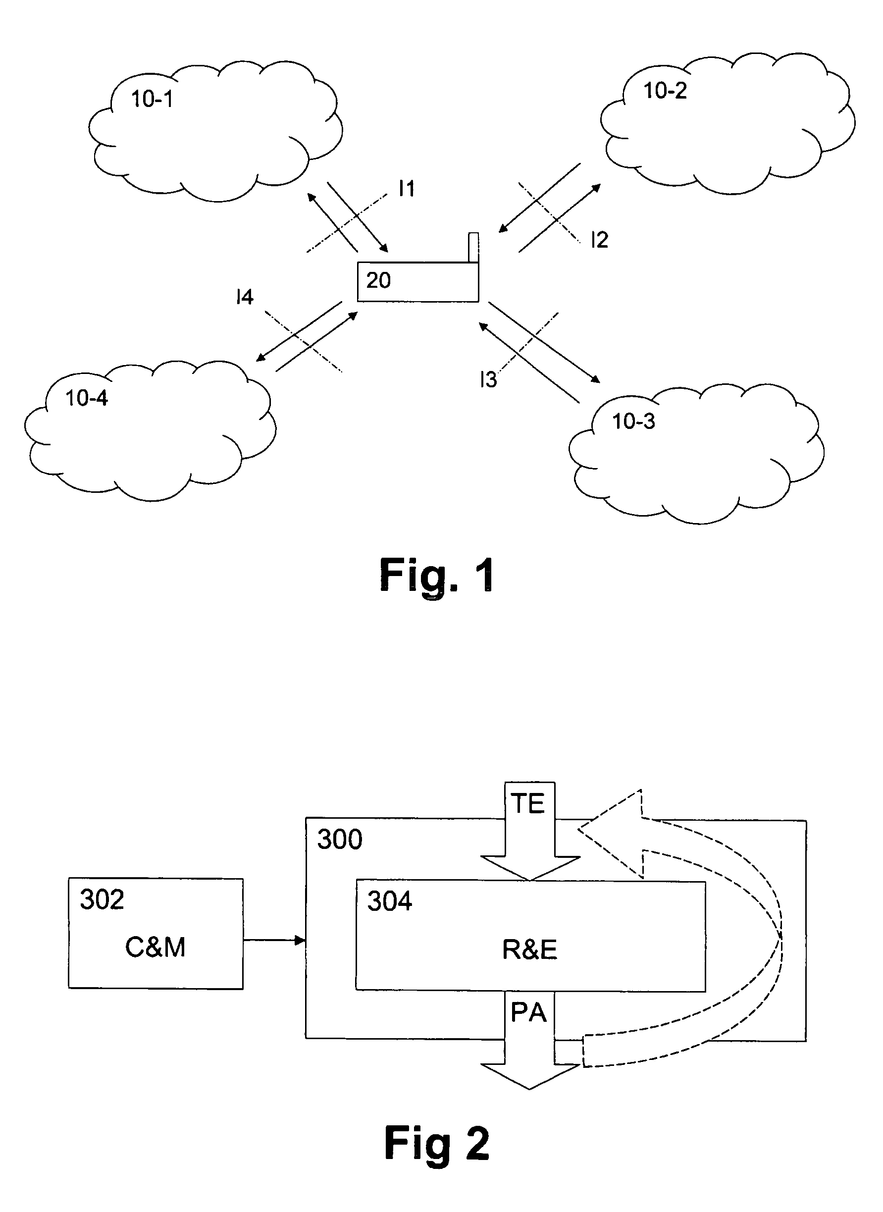
[0057]FIG. 3 shows a flow diagram of the stages of a resolution round according to the first embodiments. The set of trigger events is frozen before each round so that if there are trigger events that started after the round started, they will be postponed to the next resolution round. The policy resolution engine, as shown in FIG. 2, receives trigger events TE, including both configuration and connectivity events, from external components and classifies them based on their types. These events are received over a certain short period of time that is long enough for clearly interrelated events to take place.

[0058]According to FIG. 3, the resolution rounds consist of a first step or stage S101

[0059]In which access network availability i...

second embodiment

[0089]FIG. 5 shows a flow diagram of the network-assisted policy resolution procedure wherein the left-hand column of FIG. 5 indicates processing steps performed at the access network (AN), and the right-hand column indicates processing steps performed at the terminal device (UE). The processing block indicated middle portion of FIG. 5 relates to a processing which involves both access network and terminal device.

[0090]The access network (AN) maintains a relevant portion of the user's up-to-date preference information, and additionally it may have compatible definitions for all access points and network edge segments in the location. In step S201, the access network identifies each user's flows and is able to execute a proxy policy resolution process in step S202 in order to select an appropriate access point for the flow, using the user's preference information and its own access network definitions. The policies are enforced either transparently by the access network (as indicate...


PUM


Abstract

The present invention relates to a policy resolution method and system, access network and terminal device for enabling modular network-assisted policy resolution, wherein the policy resolution is divided into separate stages each handling specific types of trigger events and performing specific types of policy actions. The separate stages are processed in a chronological order during a policy resolution round, and trigger events which occur during a policy resolution round are frozen until the start of the next policy resolution round. Thereby, modular policy resolution with reduced delays and oscillations can be achieved. Moreover, policy processing can be divided into a policy decision point functions in the network and a policy enforcement point function in the network or terminal device, so that terminal resources used for policy resolution can be saved.

Description

CROSS-REFERENCE TO RELATED PATENT APPLICATIONS[0001]The present application claims priority to European Patent Application No. 05 022 370.0, filed Oct. 13, 2005 and incorporated herein by reference in its entirety.FIELD OF THE INVENTION[0002]The present invention relates to a method, system, network element and terminal device for policy resolution with interdependent trigger events and policy actions. In particular, the present invention relates to multi-access policy resolution.BACKGROUND OF THE INVENTION[0003]In order to make dynamic systems behave as required, the users and operators of such systems can use a set of policies that specify how the system should respond to various situations. Each policy or policy statement applies to a specific application or a set of applications, and may be specific to a logical instance of the application. It may describe a condition and a network service to be applied for traffic matching that condition. A policy statement may comprise a gener...

Claims


Application Information

Patent Timeline
Patent Type & Authority Patents(United States)
IPC IPC(8): H04L29/06H04W36/14H04W48/18H04W88/06
CPCH04L41/0893H04W48/18H04W88/06H04L12/28H04L47/10H04L47/20H04W36/14H04W28/02H04L41/0894H04W8/04
Inventor WARIS, HEIKKI
Owner NOKIA TECH OY
Learn More