
Solar array peak power extraction

a solar array and peak power technology, applied in the direction of pv power plants, transportation and packaging,cosmonautic vehicles, etc., can solve the problems of not optimizing the power generation of solar arrays, not being able to extract the maximum solar array power, and not being able to extract peak solar array power from shunt regulators

Active Publication Date: 2012-04-10
THE BOEING CO
View PDF19 Cites 14 Cited by
  • Summary
  • Abstract
  • Description
  • Claims
  • Application Information

AI Technical Summary

Benefits of technology

The patent describes an apparatus and method for optimizing power generation from a solar array on a spacecraft. The invention allows for the temporary setting of the bus voltage to a higher level to maximize solar array power extraction, while still meeting the needs of other voltage-tolerant electrical systems on the spacecraft. The control circuit uses reference signals, such as temperature sensors and a baseline reference signal, to direct the regulator to set the bus voltage. The invention can be particularly useful for spacecraft with electric propulsion systems. The technical effect of the invention is to increase the amount of solar power that can be captured and utilized by the spacecraft's electrical system.

Problems solved by technology

Because the satellite electrical systems do not change their operating voltage as the solar array Vmp changes, it is not possible to extract the maximum solar array power from a solar array at all times. Thus, power generation for the solar array is not optimized.
Therefore a shunt regulator does not extract peak solar array power at beginning-of-life (BOL).
A conventional peak power tracker system that is coupled to the batteries gives rise to another problem because the peak power tracker output is unregulated.
This would increase spacecraft mass and further reduce overall power conversion efficiency.
In any case, the conventional techniques for addressing the described power optimization problem typically introduce a relatively high insertion loss between the solar array and the power bus.
Such conventional solutions insertion loss results in power losses estimated at approximately 3% to 5% or even higher if a second stage DC-DC converter is used.
Accordingly, although peak power trackers extract some additional solar array power, their benefit is diminished as a result of their own functional losses.

Method used


Image

  • Solar array peak power extraction
  • Solar array peak power extraction
  • Solar array peak power extraction

Examples


Embodiment Construction

[0024]1. Overview

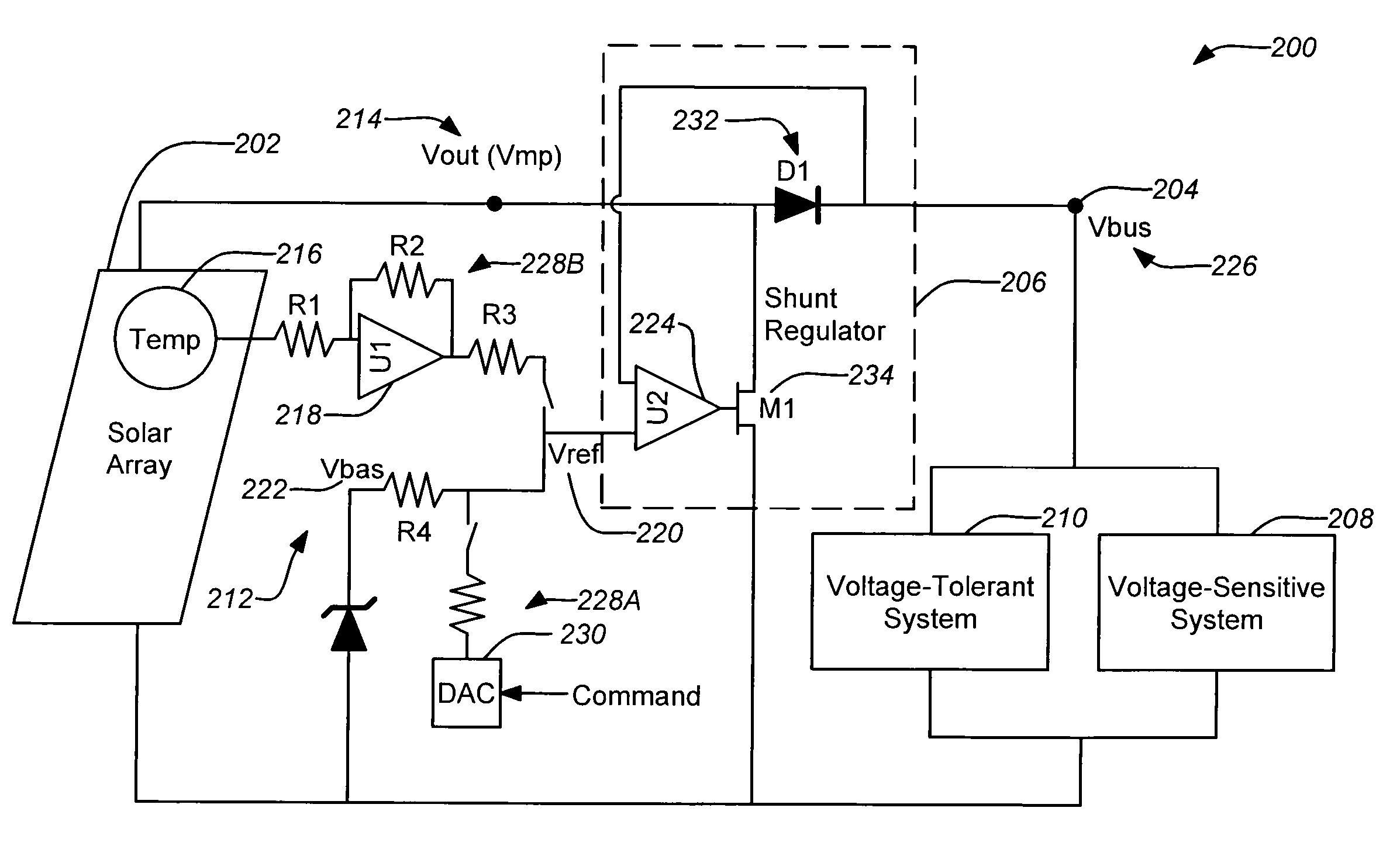
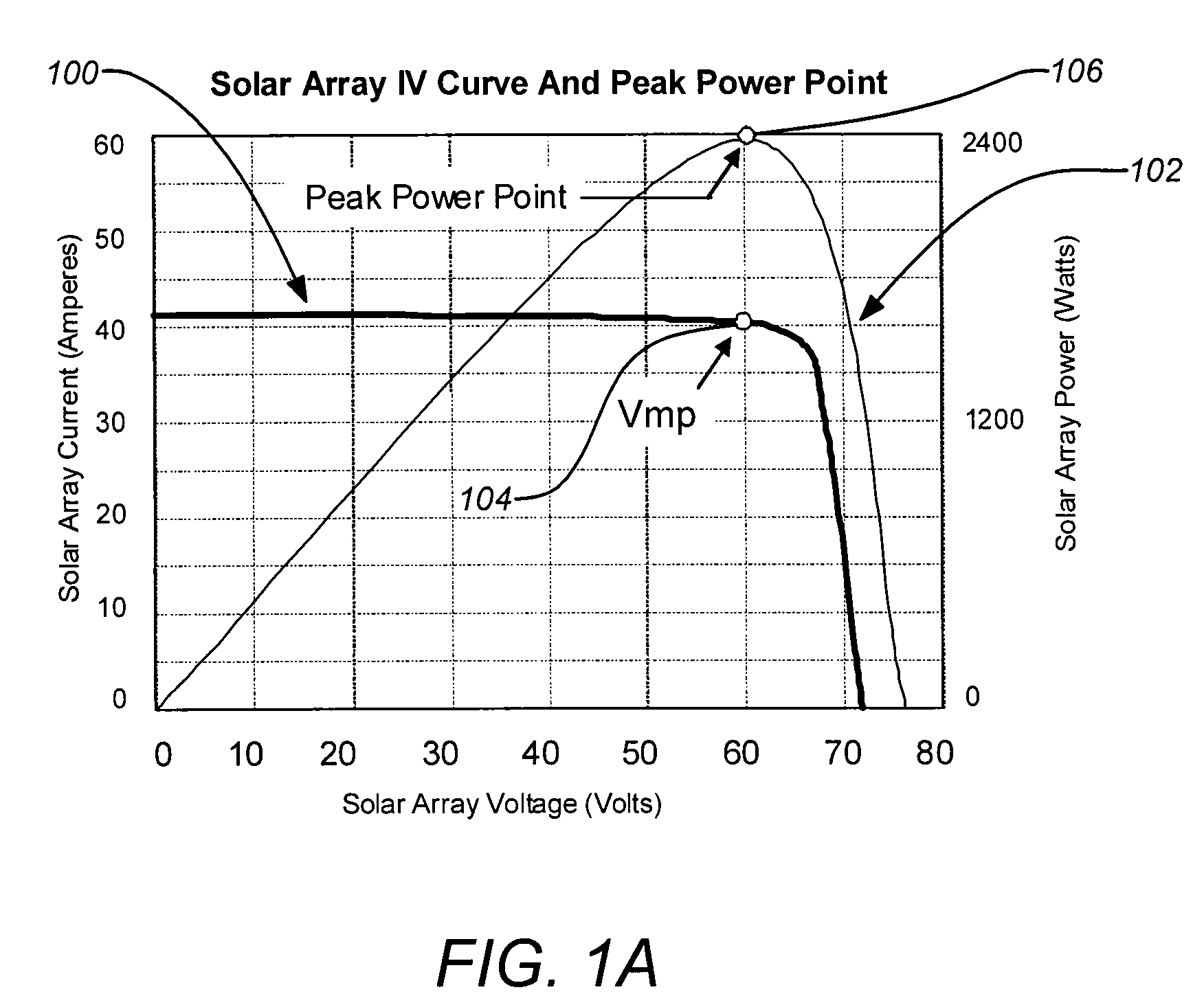
[0025]As previously mentioned, embodiments of the disclosure are directed to optimizing power generation of a solar array. Some embodiments of the disclosure can be implemented through a variable and programmable bus voltage for a satellite. The nominal bus voltage may be selected to correspond with the Vmp of the solar array based on the age-based and seasonal performance prediction for the solar array at the nominal operating temperature. The control method can be applied to modify the existing bus voltage regulation providing additional solar array power to the powered electrical systems. A conventional peak power tracker operates the solar array at Vmp, and its output is unregulated. However, Vmp is a function of temperature, illumination, cell characteristics (including aging) shadowing, and other terms and can vary greatly. A conventional peak power tracker either with a second stage DC-DC converter or a battery-on-bus topology previously described is typicall...


PUM


Abstract

Apparatuses and methods for optimizing power generation of a solar array are disclosed. The bus voltage is regulated with a regulator controlled through one or more reference signals. When the power bus is being used by electrical systems that are tolerant of a higher variable voltage range, the bus voltage can be temporarily set higher by a commanded reference signal to allow additional solar array power to supply to the power bus. The peak power point may be identified through an established relationship with the solar array performance as a function of temperature, season and / or the age of the solar array. In addition, a reference signal controlled by one or more temperature sensors on the solar array may also modify the bus voltage set-point. Improved solar array power may be extracted from spacecraft beginning-of-life to end-of-life operations due to low insertion loss of a direct energy transfer scheme.

Description

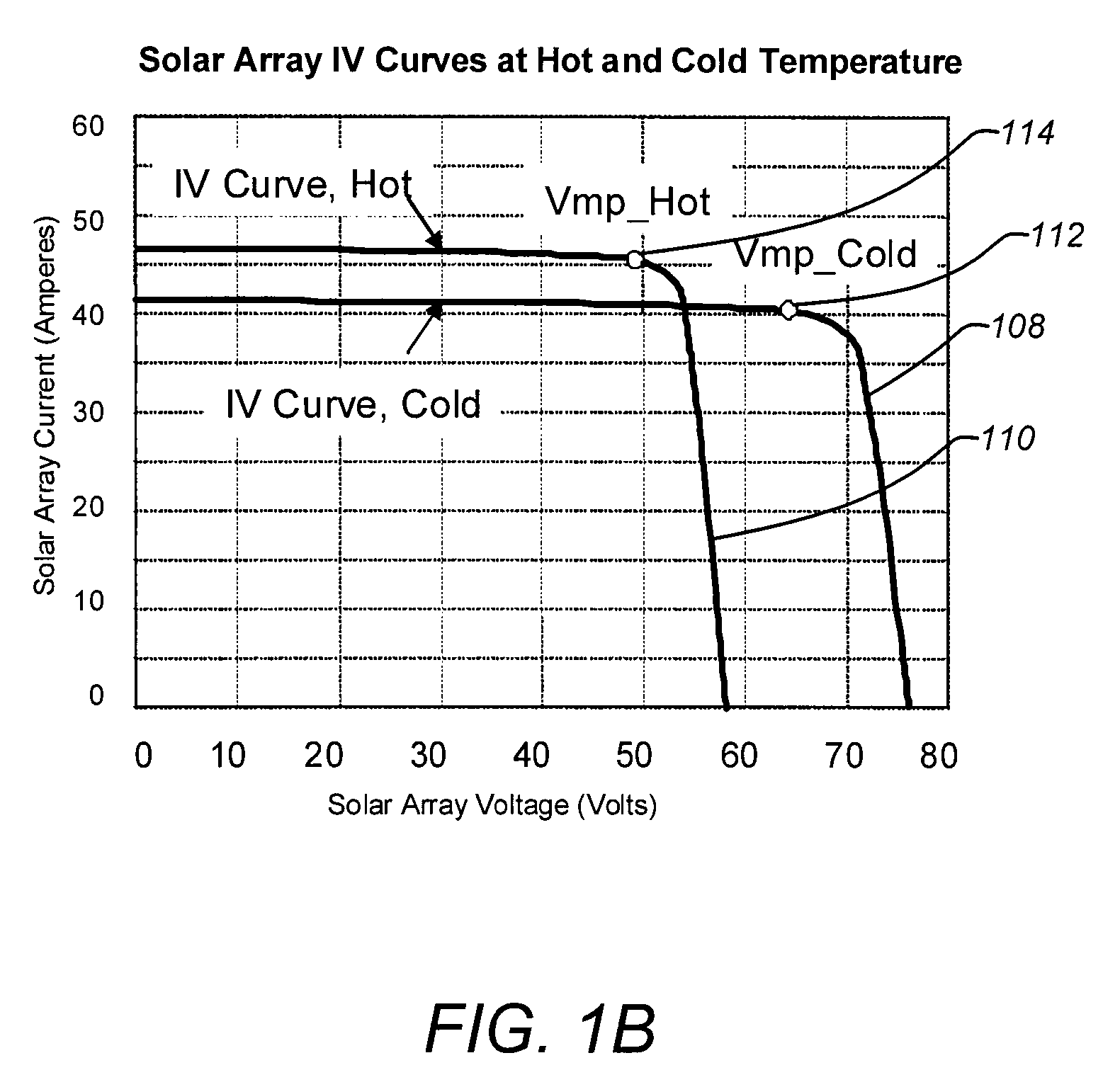
BACKGROUND OF THE DISCLOSURE[0001]1. Field of the Disclosure[0002]This disclosure relates to regulating voltage of solar arrays to optimize power generation. Particularly, this disclosure relates to regulating voltage of solar arrays to optimize power generation for space applications.[0003]2. Description of the Related Art[0004]Optimal power extraction from an illuminated solar array occurs when the operating array voltage of the solar array is at the peak power point. This array voltage at the peak power point is typically termed the Vmp, the voltage at which the maximum solar array power is generated. Typically, the Vmp is dependent on the age, season and temperature for a given solar array. When a solar array is used in a satellite, the solar array temperature frequently changes due to orbital variation and seasonal changes. The space radiation environment degrades the solar array which affects Vmp. Thus, as the satellite solar array ages, season and temperature change, so does ...

Claims


Application Information

Patent Timeline
Patent Type & Authority Patents(United States)
IPC IPC(8): B64G1/42
CPCB64G1/425B64G1/428B64G1/443H01L31/02021H02J1/14Y02E10/50
Inventor BECKER-IRVIN, CRAIG H.CHOY, WINNIE W.
Owner THE BOEING CO
Learn More