Motor-driven supercharger

a supercharger and motor technology, applied in the direction of positive displacement liquid engines, pumps, machines/engines, etc., can solve the problems of hard cooling of both the compressor impeller and the electric motor, and achieve the effect of reducing the number of parts, efficient cooling of the motor stator, and convenient assembly and disassembly

Active Publication Date: 2012-04-10
IHI CORP
View PDF149 Cites 5 Cited by
  • Summary
  • Abstract
  • Description
  • Claims
  • Application Information

AI Technical Summary

Benefits of technology

[0018]The present invention is made for solving the problem mentioned above. In other words, an object of the present invention is to provide a motor-driven supercharger which can firmly fix a stator (a motor stator) of an electric motor to a casing without necessity of any additional casing and any exclusive fixing part, and can efficiently cool both of a compressor impeller and the electric motor, in comparison with a conventional supercharger which does not have any electric motor built-in.
[0038]In accordance with the structure on the basis of the present invention mentioned above, since the outer sleeve and the motor stator construct the stator assembly as the integral part, and the outer sleeve of the stator assembly and seal plate are fastened together in the axial direction between the bearing housing ad the compressor housing, it is possible to simultaneously fix the motor stator to the bearing housing by fixing the compressor housing to the bearing housing. Accordingly, since the additional casing for fixing the motor stator 24 to the bearing housing 16 and the exclusive fixing part (the fastening device such as the bolt or the like) at a time of assembling are not necessary, and it is possible to reduce the number of the parts at a time of assembling, it is easy to assemble and disassemble.
[0039]Further, since the outer sleeve is closely attached to the outer peripheral surface of the motor stator and supports the motor stator so as to constrain the rotation of the motor stator, it is possible to firmly fix the stator (the motor stator) of the electric motor to the casing.
[0040]Further, since the stator assembly constructs the liquid tight water cooling jacket between the stator assembly and the bearing housing, the outer wall portion (the outer sleeve) of the stator assembly is directly cooled, whereby it is possible to efficiently cool the motor stator closely attached to the outer sleeve.
[0041]Further, since the seal plate comparts between the compressor housing and the motor stator, and is closely attached to the compressor side of the outer sleeve, it is possible to set a contact area therebetween sufficient wide, and it is possible to efficiently cool the seal plate heated by a compressed air on the basis of a heat transfer from the seal plate to the water cooling jacket.

Problems solved by technology

Further, since the compressor impeller is close to the stator of the electric motor, there is a problem that it is hard to cool both the compressor impeller and the electric motor.

Method used


Image

  • Motor-driven supercharger
  • Motor-driven supercharger
  • Motor-driven supercharger

Examples


Embodiment Construction

[0051]A description will be in detail given below of preferable embodiments in accordance with the present invention with reference to the accompanying drawings. In this case, in each of the drawings, the same reference numerals are attached to the common portions, and an overlapping description will be omitted.

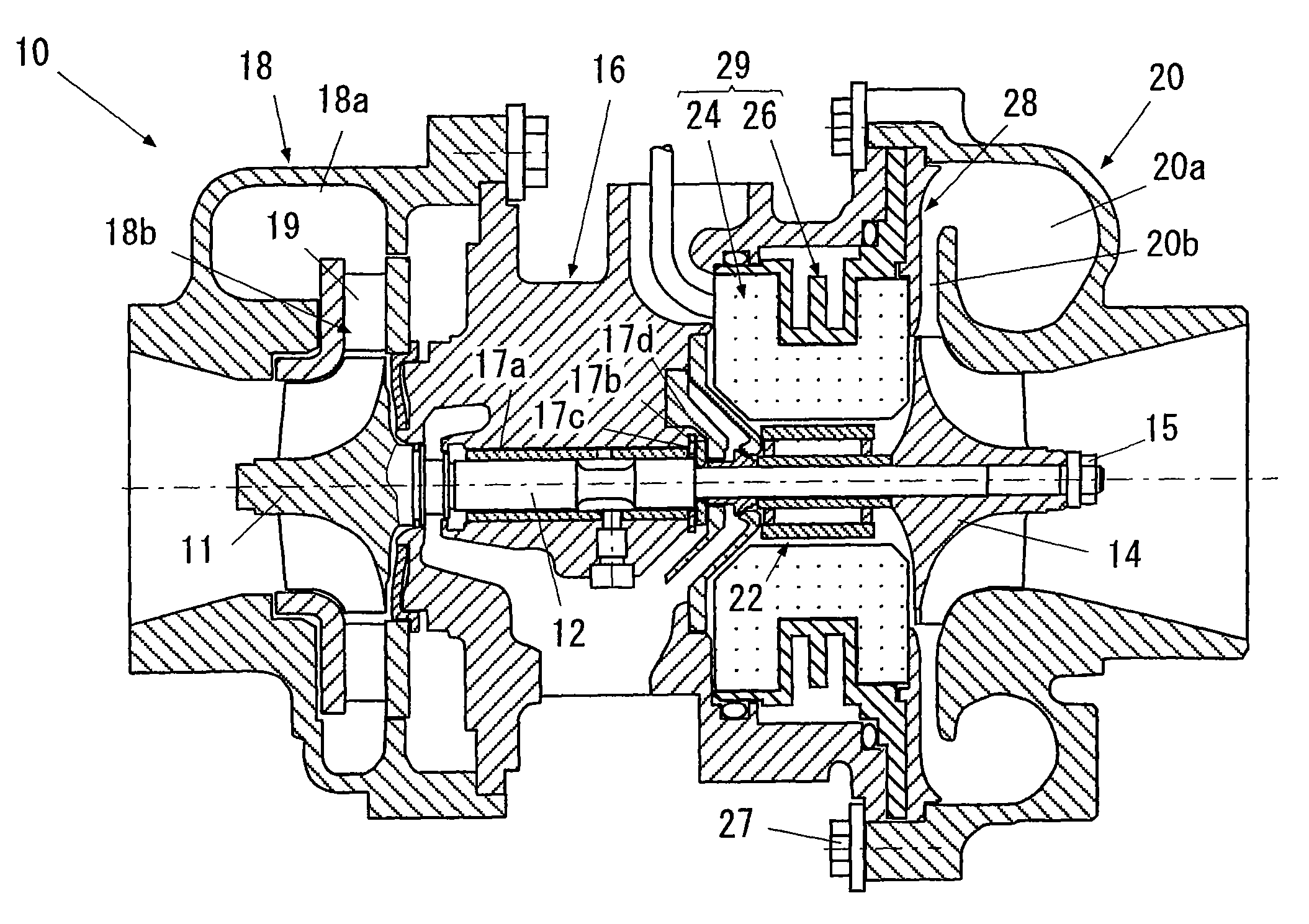
[0052]FIG. 4 is a schematic view of a whole of a motor-driven supercharger in accordance with a first embodiment of the present invention. In this drawing, a motor-driven supercharger 10 in accordance with the present invention is provided with a turbine shaft 12, a compressor impeller 14, and a housing. The housing is constituted by a bearing housing 16, a turbine housing 18 and a compressor housing 20 in this embodiment.

[0053]The turbine shaft 12 has a turbine impeller 11 in one end (a left end in the drawing). In this embodiment, the turbine impeller 11 is integrally formed in the turbine shaft 12, however, the present invention is not limited to this, but may be structure...


PUM


Abstract

A motor-driven supercharger is provided with a stator assembly inserted and attached to a bearing housing, and a seal plate closely attached to a compressor side of the stator assembly and comparting between a compressor housing and a motor stator (24). The stator assembly has the motor stator and an outer sleeve having an inner peripheral surface closely attached to an outer peripheral surface of the motor stator and supporting the motor stator in such a manner as to constrain a rotation of the motor stator, wherein the motor stator and the outer sleeve form an integral part so as to construct the stator assembly, and the outer sleeve constructs a liquid tight water cooling jacket between the outer sleeve and the bearing housing. The outer sleeve and the seal plate are fastened together in an axial direction between the bearing housing and the compressor housing.

Description

BACKGROUND OF THE INVENTION[0001]1. Field of the Invention[0002]The present invention relates to a motor-driven supercharger having an electric motor built-in.[0003]2. Description of the Related Art[0004]To supply an air having a density increased by a compressor to an engine is called supercharging, and a structure providing for a driving work of the compressor on the basis of an exhaust energy is called as an exhaust-gas turbocharger.[0005]The exhaust-gas turbocharger is generally constituted by a compressor and a turbine which are arranged so as to sandwich a bearing unit therebetween. The compressor has a compressor impeller built-in, and the turbine has a turbine impeller built-in, respectively. The compressor impeller and the turbine impeller are coupled to each other by a connecting shaft (a shaft) supported by a bearing unit, and are structured such as to rotationally drive the turbine impeller on the basis of an exhaust gas of the engine, transmit the rotating force to the ...

Claims


Application Information

Patent Timeline
Patent Type & Authority Patents(United States)
IPC IPC(8): F04B35/00
CPCF01D15/10F01D25/12F01D25/14F01D25/24F02B37/025F02B37/10F02B39/005F02B39/10F02C6/12F05D2220/40F05D2220/76F05D2230/60F05D2260/232Y02T10/144Y02T10/12F02B37/04F02B39/02
Inventor SHIMIZU, MASAHIROSHIBUI, YASUYUKI
Owner IHI CORP
Why Eureka
Try Eureka