Molten optical glass fining apparatus

a technology of optical glass and fining apparatus, which is applied in the field of manufacture of high-quality glass, can solve the problems of high cost of fabrication, difficult to remove from glass, and the view of bubbles as defects in any glass product which requires optical properties, so as to improve the fining capability of the apparatus and reduce the distance to rise, the effect of improving the fining performan

Active Publication Date: 2012-04-17
CORNING INC
View PDF46 Cites 2 Cited by
  • Summary
  • Abstract
  • Description
  • Claims
  • Application Information

AI Technical Summary

Benefits of technology

[0018]The present invention significantly modifies the currently known fining apparatus (finer). The basic shape is changed from a cylindrical shape to an elliptical shape, a somewhat rectangular shape, variations on a gabled roof shape, or variations on a gothic arch shape, such that the flow is more uniform and the seeds have less distance to rise to the surface. Baffles of a novel design are optionally included in an embodiment of the present invention to further increase fining performance. Prior art baffle designs are optionally included in an embodiment of the present invention to trap seeds and serve as structural elements. The present invention improves the fining capability of the apparatus without increasing the cost of construction materials. In fact, the cost would be reduced for the same fining performance by shortening the length of the finer.

Problems solved by technology

These bubbles are considered defects in any glass product which requires optical properties.
The finer is often very large, resulting in extremely high costs to fabricate because the glass contact surfaces are constructed of platinum or platinum alloy.
Seeds are the primary concern as they are small in diameter and thus are more difficult to remove from the glass.
This introduces contamination and can also generate additional seeds in the glass.

Method used


Image

  • Molten optical glass fining apparatus
  • Molten optical glass fining apparatus
  • Molten optical glass fining apparatus

Examples


Embodiment Construction

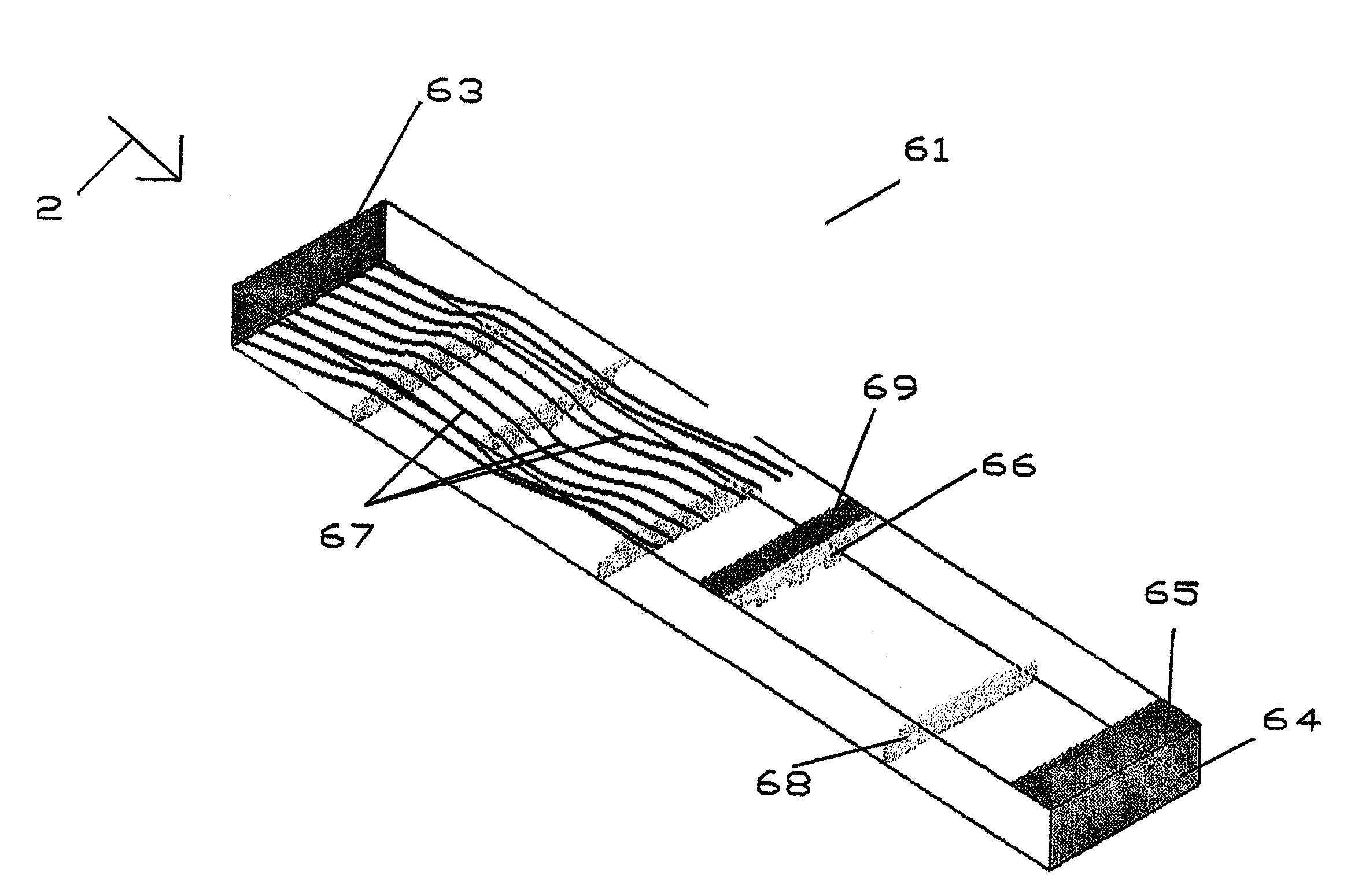
[0097]In all embodiments of this invention, all glass contact surfaces (walls) are preferably either fabricated from platinum or are clad with platinum in some manner.

[0098]Operating at the highest practical temperature is desirable. This temperature is limited by the high temperature physical properties of the platinum and / or platinum alloy used in the fining apparatus. Structural elements made of platinum, including webs and struts both external and internal, are preferably added to the surfaces of the platinum cylinder to prevent excessive deformation for the expected duration of the production campaign.

[0099]Platinum is extremely expensive compared to the refractory material and steel required to construct the fining apparatus. The platinum required for the construction of an optical finer can cost in the millions of dollars. Controlling the quantity of platinum used to construct the fining apparatus substantially determines the cost of the fining apparatus. In this patent appli...


PUM

PropertyMeasurementUnit
angleaaaaaaaaaa
included angleaaaaaaaaaa

Abstract

The present invention significantly modifies the currently known fining apparatus (finer). The basic shape is changed from a cylindrical shape to an elliptical shape, a somewhat rectangular shape, variations on a gabled roof shape, or variations on a gothic arch shape, such that the flow is more uniform and the seeds have less distance to rise to the surface. Baffles of a novel design are optionally included in an embodiment of the present invention to further increase fining performance. Prior art baffle designs are optionally included in an embodiment of the present invention to trap seeds and serve as structural elements. The present invention improves the fining capability of the apparatus without increasing the cost of construction materials. In fact, the cost would be reduced for the same fining performance by shortening the length of the finer.

Description

REFERENCE TO RELATED APPLICATIONS[0001]This application claims an invention that was disclosed in Provisional Application Ser. No. 60 / 771,642, filed Feb. 9, 2006, entitled “MOLTEN OPTICAL GLASS FINING APPARATUS. The benefit under 35 USC §119(e) of the United States provisional application is hereby claimed, and the aforementioned application is hereby incorporated herein by reference.[0002]In addition, this is a continuation-in-part of co-pending patent application Ser. No. 10 / 745,082, filed Nov. 21, 2003, entitled “MOLTEN OPTICAL GLASS FINING APPARATUS”, which claims an invention which was disclosed in Provisional Application No. 60 / 438,875, filed Jan. 9, 2003, entitled “MOLTEN GLASS FINING APPARATUS”. The benefit under 35 USC §119(e) of the U.S. provisional application is hereby claimed, and the aforementioned applications are hereby incorporated herein by reference.BACKGROUND OF THE INVENTION[0003]1. Field of the Invention[0004]This invention relates generally to the manufacture ...

Claims


Application Information

Patent Timeline
Patent Type & Authority Patents(United States)
IPC IPC(8): C03B5/182C03B5/225C03B5/20
CPCC03B5/182C03B5/225
Inventor PITBLADDO, RICHARD B.
Owner CORNING INC
Why Eureka
Try Eureka