
Saddle-ride type vehicle

a saddle-ride type, vehicle technology, applied in cycle equipment, cycle, gear, etc., can solve the problem of reducing the cooling capacity of the v-belt continuously variable transmission, and achieve the effect of improving the cooling capacity and downsizing the body cover

Active Publication Date: 2012-04-17
YAMAHA MOTOR CO LTD
View PDF10 Cites 11 Cited by
  • Summary
  • Abstract
  • Description
  • Claims
  • Application Information

AI Technical Summary

Benefits of technology

[0010]In view of these drawbacks of the prior art, the present invention provides both improved cooling capacity for a V-belt continuously variable transmission and downsizing of the body cover.
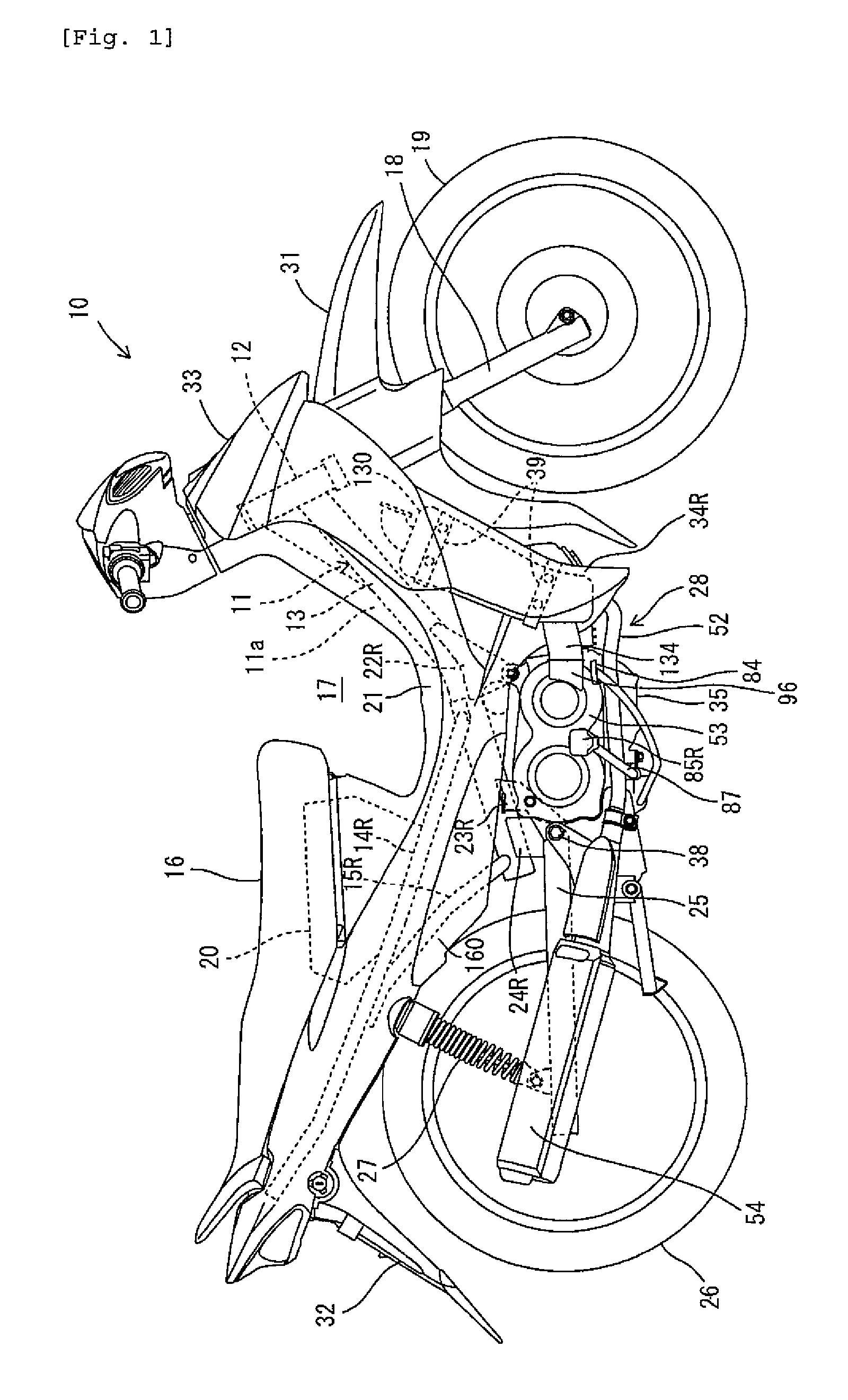
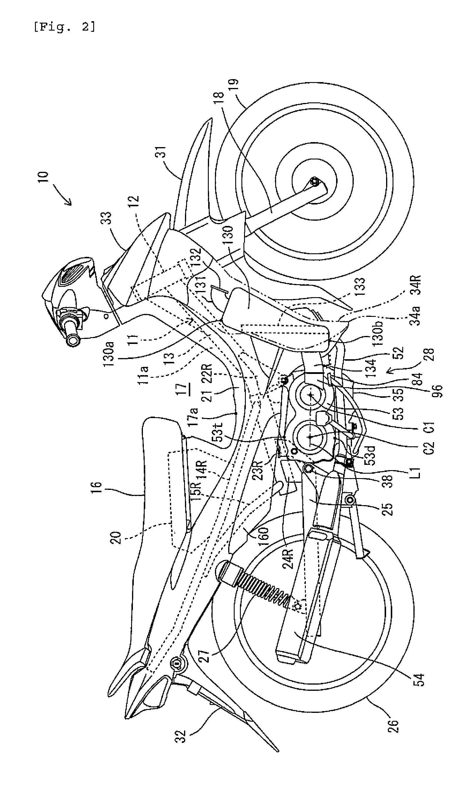
[0012]According to the invention, since at least a part of the air passage is arranged between the transmission case and the leg shield, a space between the transmission case and the leg shield is effectively used as a space in which the air passage is provided. Therefore, an air passage having enough flow passage sectional area is formed without upsizing the vehicle body cover. Accordingly, both improved cooling capacity and downsizing of the vehicle body cover are provided.
[0013]According to the invention, both improved cooling capacity for a V-belt continuously variable transmission and downsizing of the vehicle body cover in a saddle-ride type vehicle are provided.

Problems solved by technology

On the other hand, when the intake duct is decreased in diameter in order to decrease the vehicle body cover size, there is not enough flow passage cross sectional area (intake passage) in the intake duct, and the cooling capacity for the V-belt continuously variable transmission is decreased.

Method used


Image

  • Saddle-ride type vehicle
  • Saddle-ride type vehicle
  • Saddle-ride type vehicle

Examples


first embodiment

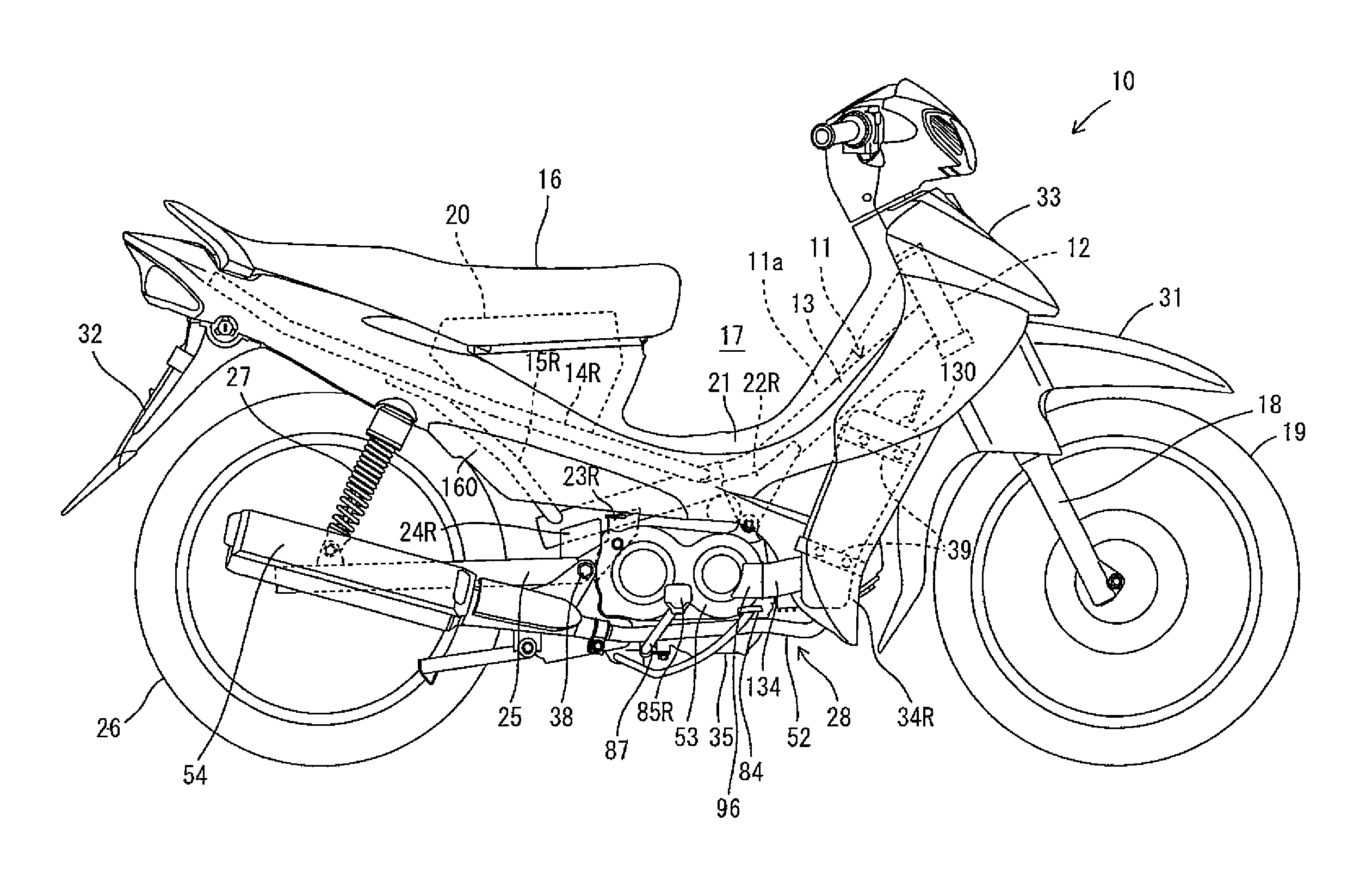
[0031]As shown in FIG. 1, a saddle-ride type vehicle according to a first embodiment of the invention is a motorcycle 10. The motorcycle 10 comprises a vehicle body frame 11, which makes a framework, and a seat 16, on which a passenger is seated. The motorcycle 10 is a so-called moped type motorcycle. That is, the motorcycle 10 includes a space 17 formed forwardly of the seat 16 to be recessed downward and shaped concave as viewed in side view, and a passenger seated on the seat 16 straddles the vehicle body frame 11 to ride. As used in the following description, “moped type” refers to a kind of vehicle in terms of shape, but provides no limitation in maximum speed, displacement, magnitude, etc. of a vehicle.

[0032]The saddle-ride type vehicle according to the invention is not limited to a moped type motorcycle but may be a motorcycle of other type such as, for example, a motorcycle type in which a fuel tank is arranged forwardly of a seat.

[0033]In the following description, front an...

second embodiment

[0116]As shown in FIG. 1, according to the first embodiment, the intake duct 134 extends forwardly of the transmission case 53 and the air chamber 130 extends from around a lower end of the leg shield 34R to around an intermediate portion thereof in the vertical direction. In contrast, as shown in FIG. 12, according to a second embodiment of the invention, an air chamber 141 is arranged above an intermediate portion of a leg shield 34R and a part of an intake duct 142 extends obliquely upward along the leg shield 34R.

[0117]According to the second embodiment, the intake duct 142 is connected to a first bulge portion 93 (see FIG. 7) of a transmission case 53 from obliquely upward. The intake duct 142 extends forwardly and obliquely upwardly of the transmission case 53 to be bent upward at the back of the leg shield 34R, and then extends obliquely upward along the leg shield 34R to be connected to the air chamber 141.

[0118]The air chamber 141 is arranged in a position above a lower end...

third embodiment

[0121]According to the first embodiment and the second embodiment, an intake passage, through which air is introduced into belt chamber 67, is provided between the transmission case 53 and the leg shield 34R. In contrast, according to a third embodiment of the invention, an exhaust passage, through which air discharged from a belt chamber 67 is led, is provided between a transmission case 53 and a leg shield 34R as shown in FIG. 13.

[0122]That is, according to the third embodiment, an exhaust duct 151 is connected to a connecting pipe 96 of the transmission case 53. The exhaust duct 151 is extended forwardly of the transmission case 53 and curved obliquely upward and rearwardly of the leg shield 34R. Further, the upwardly curved exhaust duct 151 is curved downward above an intermediate portion of the leg shield 34R in a vertical direction to extend to the vicinity of a lower end 34a of the leg shield 34R. A downstream end 151a of the exhaust duct 151 is opened downward. In addition, ...


PUM


Abstract

Improved cooling capacity for a V-belt continuously variable transmission that is compatible with miniaturization of a vehicle body cover is provided in a saddle-ride type vehicle. A concave-shaped space recessed downward is compartmented forward of a seat by a vehicle body cover. An engine unit is supported by the vehicle body frame below the concave-shaped space. The engine unit includes a transmission case formed with a belt chamber in which a V-belt continuously variable transmission is accommodated. An intake duct defines an air passage communicated to the belt chamber. The intake duct is arranged between the transmission case and a leg shield.

Description

RELATED APPLICATIONS[0001]This application claims the benefit of priority under 35 USC 119 of Japanese patent application no. 2005-222917, filed on Aug. 1, 2005, which application is hereby incorporated by reference in its entirety.BACKGROUND OF THE INVENTION[0002]1. Field of the Invention[0003]The present invention relates to a saddle-ride type vehicle provided with a V-belt continuously variable transmission.[0004]2. Description of Related Art[0005]Motorcycles including a V-belt continuously variable transmission are well known (see, for example, JP-A-2002-130440).[0006]The V-belt of a V-belt continuously variable transmission increases in temperature during travel due to frictional heat, etc. Frequently, air is supplied from the outside to a belt chamber in which the V-belt is accommodated to forcedly cool the V-belt.[0007]The motorcycle disclosed in JP-A-2002-130440 has a vehicle body frame that is substantially V-shaped as viewed from the side. The vehicle body frame is covered...

Claims


Application Information

Patent Timeline
Patent Type & Authority Patents(United States)
IPC IPC(8): B60K11/06B62J17/06B62J99/00B62K11/04B62K11/06B62M9/04F16H9/12F16H57/02F16H57/035F16H57/04
CPCB62J17/06B62K19/48F16H57/0415F16H57/0489B62K2202/00
Inventor ISHIDA, YOUSUKEOISHI, AKIFUMI
Owner YAMAHA MOTOR CO LTD
Learn More