
Melting furnace with agitator

a technology of melting furnace and agitator, which is applied in the direction of furnaces, lighting and heating apparatus, transportation and packaging, etc., can solve the problems of high cost, large amount of electric power, and inability to ignore the adverse effects of workers, and achieve the effect of low cos

Active Publication Date: 2012-04-17
TAKAHASHI KENZO
View PDF91 Cites 31 Cited by
  • Summary
  • Abstract
  • Description
  • Claims
  • Application Information

AI Technical Summary

Benefits of technology

The system effectively agitates melts with lower power consumption (0.72 kW / ton compared to 1.6-3.75 kW / ton for conventional systems) and reduces maintenance costs by eliminating the need for three-phase alternating current coils, while ensuring safe operation at high temperatures.

Problems solved by technology

Accordingly, adverse effects on workers cannot be ignored.
Accordingly, a large amount of electric power is required.
The cooling process must be carefully performed, and the system for the cooling is complicated and requires a high cost.
Since the entire system is very expensive, the employment thereof represents an investment.
Accordingly, it is not possible to easily employ such a system.

Method used


Image

  • Melting furnace with agitator
  • Melting furnace with agitator
  • Melting furnace with agitator

Examples


Embodiment Construction

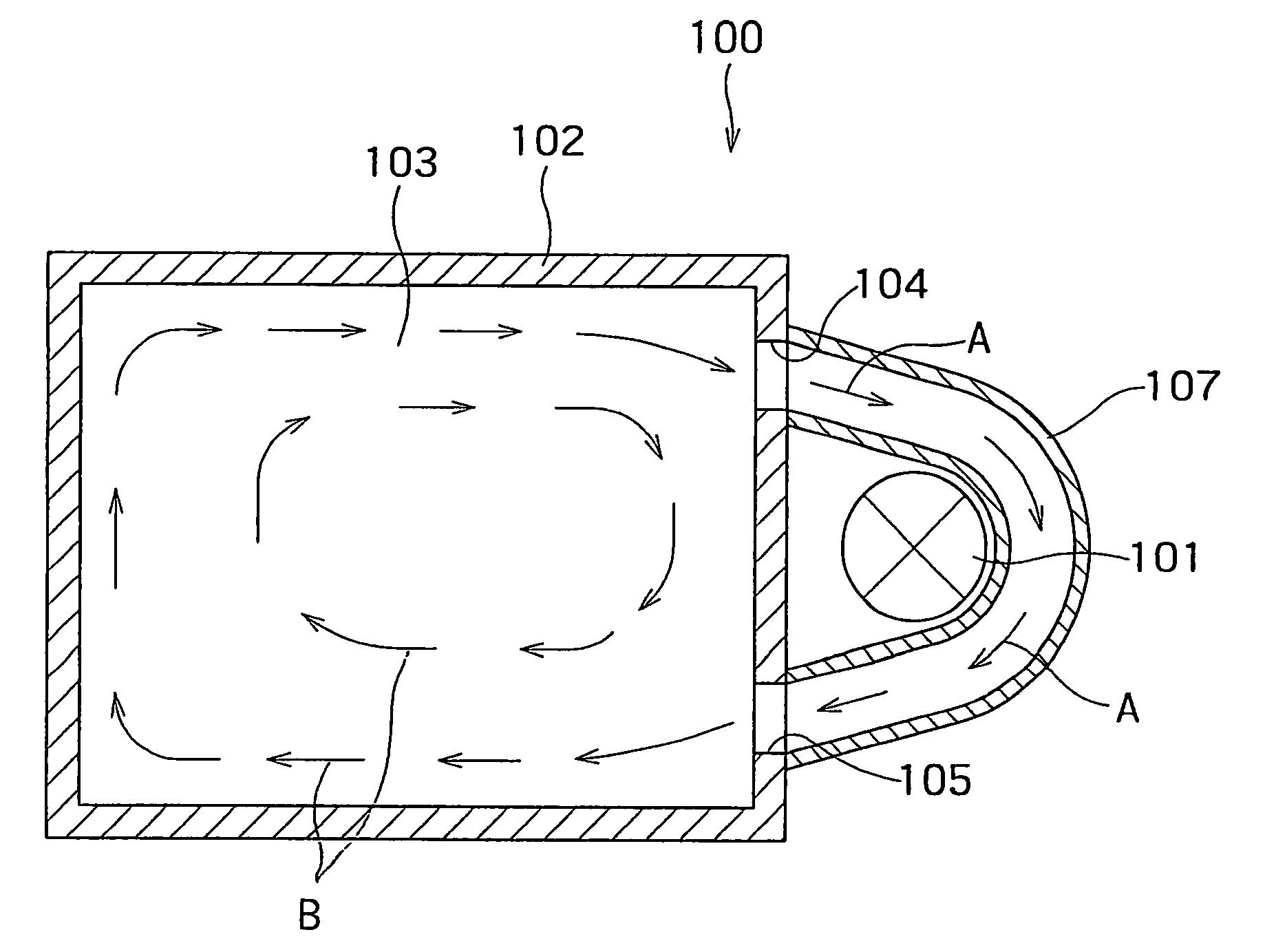
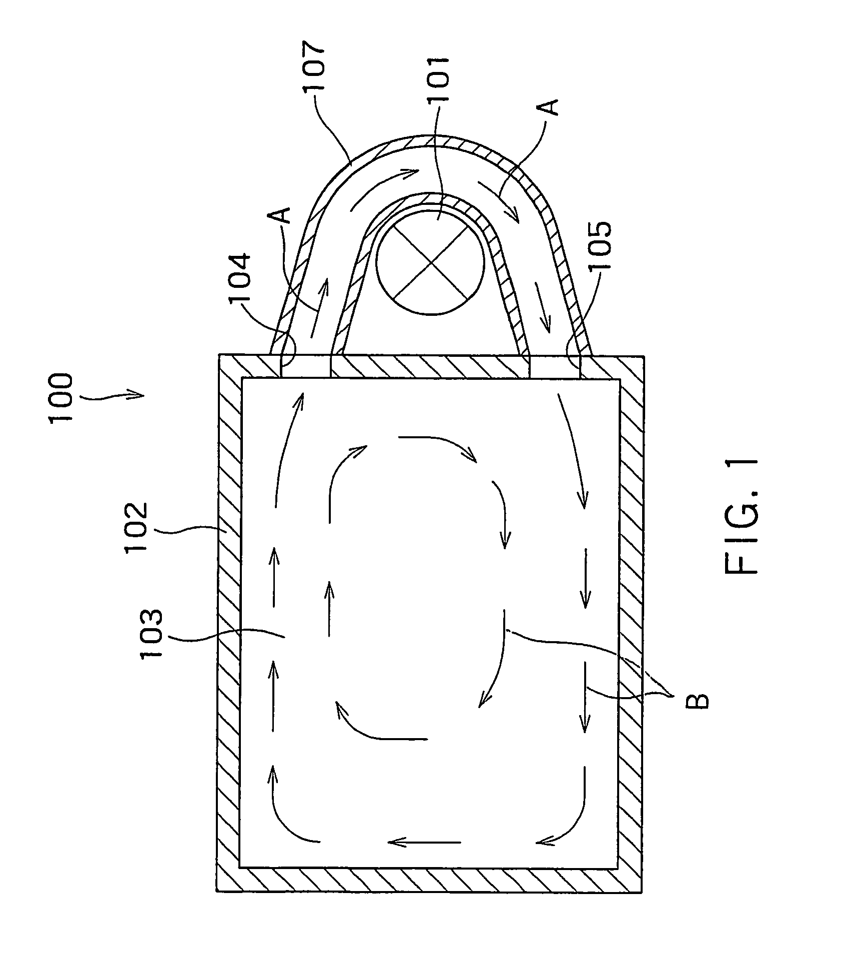
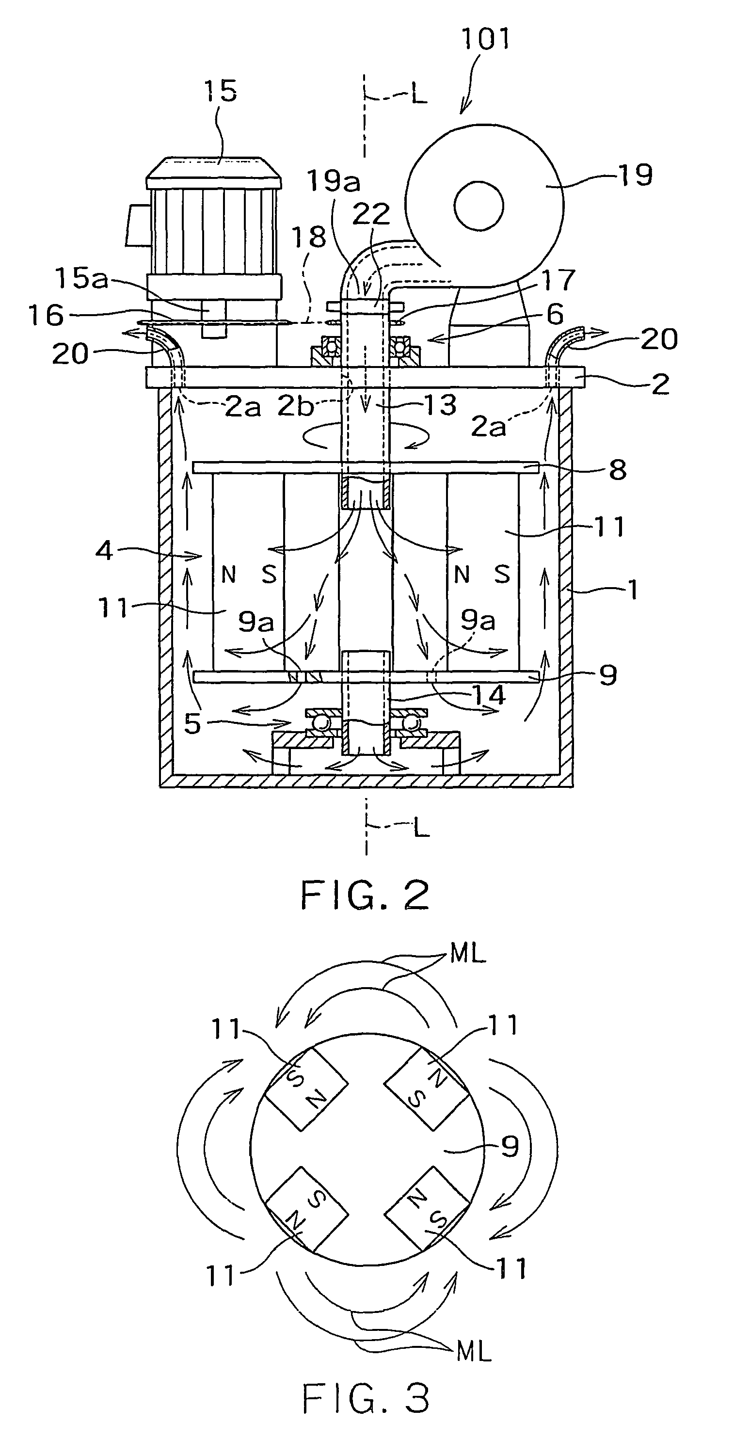
[0019]FIG. 1 shows, in a planar manner, the entire structure of a melting furnace system (melting furnace with an agitator) 100 incorporating an agitator 101 according to the present invention. As a melting furnace (melting furnace main body) 102, a conventional or existing one can be used. The melting furnace 102 is configured to heat and melt, by various kinds of burners (not shown), scrap or the like of a nonferrous material such as aluminum (a nonferrous material such as Al, Cu, Zn, an alloy of at least two of these materials, and a conductive nonferrous metal such as an Mg alloy) which is put thereinto. It is apparent that besides melting furnaces for melting nonferrous metals, the present invention can be applied to some melting furnaces for melting other metals. On one of the four sidewalls of the melting furnace 102, a melt outlet 104 and a melt inlet 105 are opened. The melt outlet 104 and the melt inlet 105 are connected by a U-shaped melt passage member 107 of a fire-resi...


PUM

PropertyMeasurementUnit
angleaaaaaaaaaa
rotations frequencyaaaaaaaaaa
melt agitation speedaaaaaaaaaa

Abstract

An agitator for agitating a melt includes a heat-resistive container having a blast opening through which cooling air is blown and an exhaust opening for exhausting air having been subjected to heat exchange, and a rotating magnet assembly composed of a permanent magnet housed in the heat-resistive container in a rotatable manner, magnetic lines of force emitted from the permanent magnet penetrating through the heat-resistive container to exit outside, and then penetrating the heat-resistive container again to return to the permanent magnet.

Description

CROSS-REFERENCE TO RELATED APPLICATION[0001]This application is based upon and claims the benefit of priority from prior Japanese Patent Application Nos. 2004-371236 and 2005-2938, filed on Dec. 22, 2004 and Jan. 7, 2005, respectively, the entire contents of which are incorporated herein by reference.BACKGROUND OF THE INVENTION[0002]1. Field of the Invention[0003]The present invention relates to an agitator, an agitating method, and a melting furnace with an agitator.[0004]2. Background Art[0005]Conventionally, ingots serving as commercial products are made from a conductive melt of a metal, a nonferrous metal and other materials. The conductive melt is a melted conductive material of Fe, Al, Cu, Zn, Pb, Ti, Mg, or an alloy or composite of at least two of these materials. On such an occasion, in order to obtain ingots having uniform quality, it is necessary to fully agitate aluminum, etc. in the melting furnace. For this reason, a stirring rod is put into a melting furnace to manual...

Claims


Application Information

Patent Timeline
Patent Type & Authority Patents(United States)
IPC IPC(8): B01F13/08F27D27/00
CPCB01F5/102B01F13/0809F27B17/00F27D27/00H02K44/06B01F2215/0075B01F25/51B01F33/451B01F2101/45
Inventor TAKAHASHI, KENZO
Owner TAKAHASHI KENZO
Learn More