
Integrated dissolution processing and sample transfer system

a technology of integrated dissolution and sample transfer, which is applied in the field of dissolution testing, can solve the problems of inaccuracy of dissolution rate, full minute of disruption of vessel hydrodynamics to withdraw a single 10-ml sample, and inability to accurately determine the dissolution ra

Active Publication Date: 2012-04-17
SOTAX CORP
View PDF4 Cites 8 Cited by
  • Summary
  • Abstract
  • Description
  • Claims
  • Application Information

AI Technical Summary

Problems solved by technology

One disadvantage of using such large-volume samples is that the samples may contain undissolved particles that dissolve during the transfer process (termed secondary dissolution), resulting in inaccurate values for the dissolution rate.
Another disadvantage of large-volume samples is that the vessel hydrodynamics are disrupted for the entire time the sample is being withdrawn from the vessel.
For example, a typical transfer rate is 10 ml per minute, resulting in a full minute of disruption of the vessel hydrodynamics to withdraw a single 10-ml sample.
In addition, withdrawing multiple large samples necessitates replenishing the sample media in the test vessel to maintain adequate volume for proper agitation of the mixture, adding complexity to the process.
Disadvantages of using tubing to transfer the samples include the inconvenience of purging the tubing after each sample is transferred and the risk of carryover (i.e., contamination) if purging is incomplete.
Components of the sample may also adsorb to the inner surface of the tubing, producing an inaccurate dissolution rate.
Another disadvantage of prior art instruments is their inability to handle all possible dosage forms within a single test run or to handle the different dosage forms without modifying the instrument for each different dosage form.
Typically prior art systems are not able to handle tablets (and other dosage forms that are dispensed directly into the dissolution media) along with sinkers and baskets all within a single run.

Method used


Image

  • Integrated dissolution processing and sample transfer system
  • Integrated dissolution processing and sample transfer system
  • Integrated dissolution processing and sample transfer system

Examples


Embodiment Construction

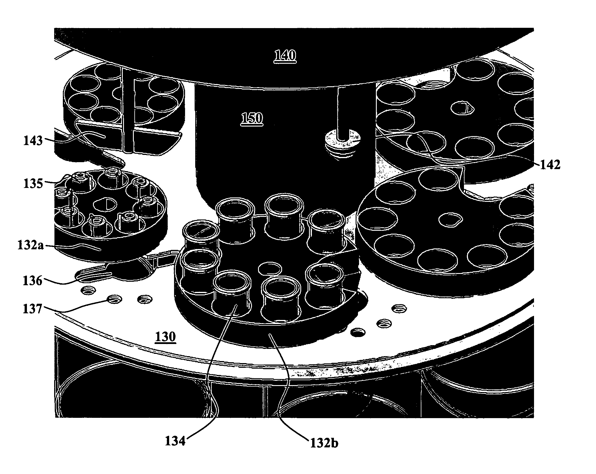
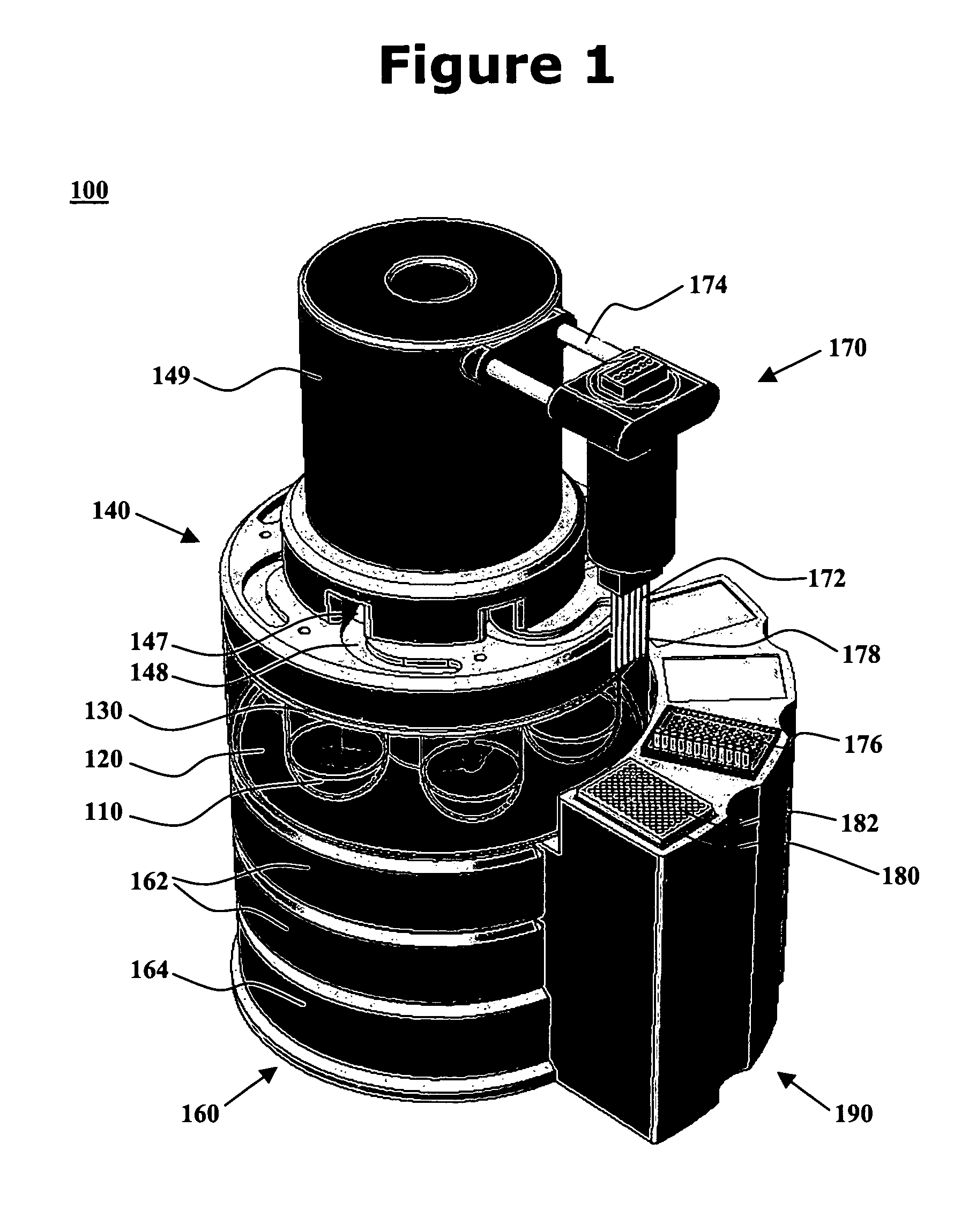
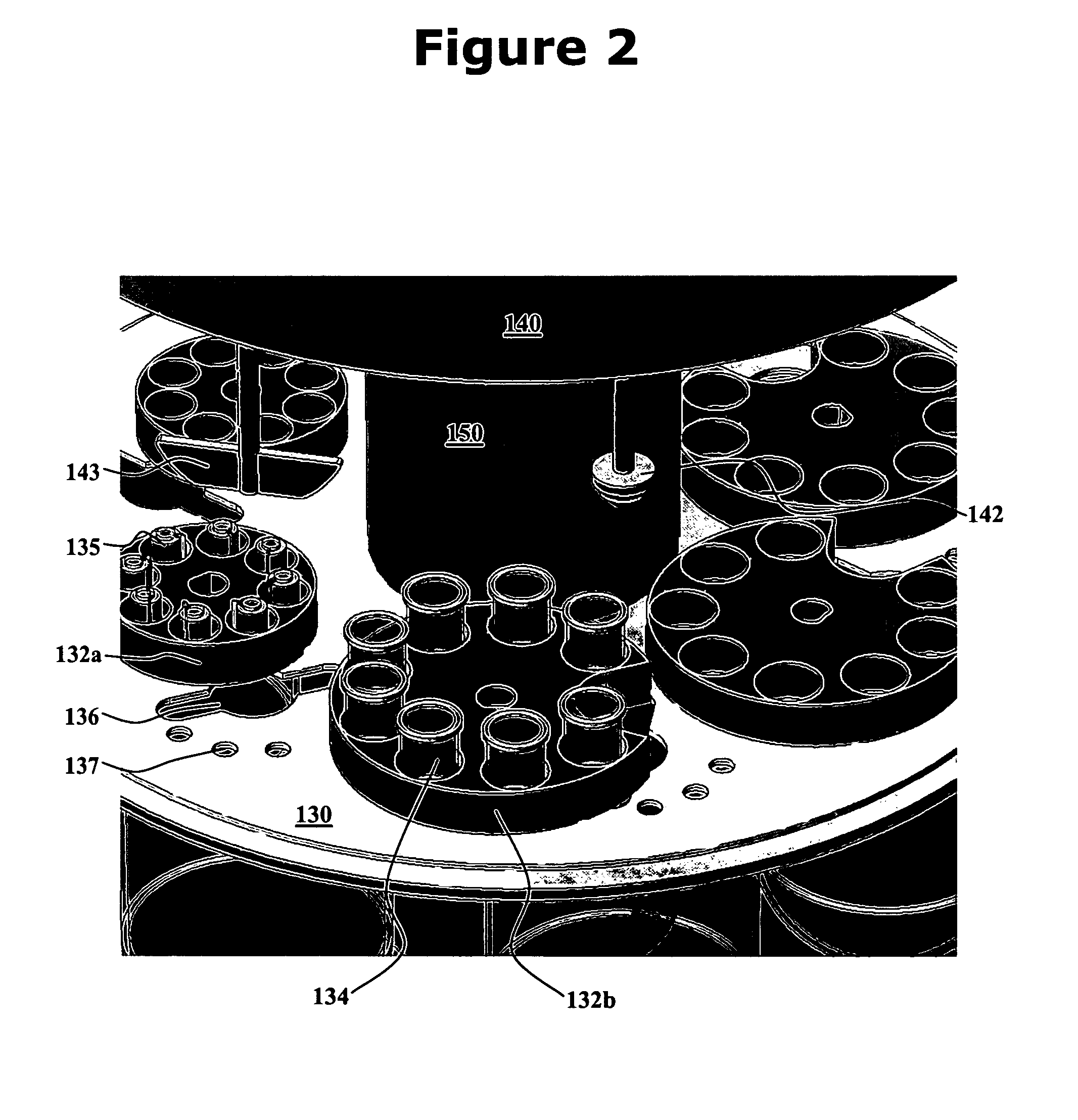
[0016]One aspect of the present invention is an integrated dissolution processing and sample transfer system. One embodiment of the system, in accordance with the present invention, is illustrated at 100 in FIGS. 1-3. The illustrated system comprises a plurality of dissolution vessels 110, a water bath 120, a dose ring 130, a drive head 140, a central shaft 150, a base 160, a sample transfer device 170, an external receptacle 180, and an external receptacle support structure 190. Dose ring 130 includes removable carousels 132 configured with cavities 133 to receive baskets 134 or sinkers / tablets 135. Openings 136 and 137 are formed in dose ring 130. Drive head 140 includes fixtures 141 to hold a basket arbor 142 or a mixing paddle 143, cannulae 144 having electromagnets 145, a clean-in-place nozzle 146, sinker diversion structures 147, sinker collection trays 148, and a turret 149. Base 160 includes one or more tanks 162 as well as space 164 for components such as electronic control...


PUM

PropertyMeasurementUnit
volumesaaaaaaaaaa
physicalaaaaaaaaaa
temperatureaaaaaaaaaa

Abstract

The invention provides a system and method for dissolution testing. The system includes multiple dissolution vessels and a dose carrier positioned above the dissolution vessels. The dose carrier holds multiple removable carousels that receive individual doses for dissolution tested. Carousels that receive tablets or sinkers typically have a first configuration, while carousels that receive baskets typically have a second configuration. The two different configurations of carousels are interchangeable on the same dose ring. The system further includes a drive head positioned above the dose carrier, the drive head having a basket arbor and a mixing paddle removably and interchangeably attached. A pipettor integral with the system transfers sample aliquots having volumes in the range of 50 μl to 1 ml from the dissolution vessels to wells of an external receptacle.

Description

CROSS REFERENCE TO RELATED APPLICATION[0001]This application claims the benefit of U.S. Provisional Application No. 60 / 755,025, filed Dec. 30, 2005, which is incorporated herein by reference in its entirety for all purposes.TECHNICAL FIELD[0002]This invention relates generally to the field of dissolution testing. More particularly, the invention relates to an integrated dissolution processing and sample transfer system.BACKGROUND OF THE INVENTION[0003]Dissolution testing involves physical evaluation of solid dosage forms such as capsules and tablets. Results of dissolution testing are useful in studying drug release characteristics of the dosage form and evaluating equipment and processes used in forming individual doses. To ensure uniformity in testing, entities such as the United States Pharmacopeia (USP) and the European Pharmacopeia provide guidelines for equipment used in dissolution testing.[0004]Under these guidelines, typically a capsule or tablet is deposited in a test vess...

Claims


Application Information

Patent Timeline
Patent Type & Authority Patents(United States)
IPC IPC(8): G01N21/00
CPCG01N13/00G01N1/38G01N33/15G01N35/025G01N2013/003G01N2013/006G01N2035/00198
Inventor KENNEDY, COLINHUSAIN, SYEDVON BEHREN, DALEBERNAL, RICK
Owner SOTAX CORP
Learn More