Method of improving print performance in flexographic printing plates

a printing plate and flexographic technology, applied in the direction of photosensitive materials, instruments, photomechanical equipment, etc., can solve the problems of affecting the printing performance of corrugated board substrates, affecting the printing effect, and often having slight indentations on the liner layer, etc., and achieve good results

Active Publication Date: 2012-04-17
MACDERMID PRINTING SOLUTIONS
View PDF39 Cites 89 Cited by
  • Summary
  • Abstract
  • Description
  • Claims
  • Application Information

AI Technical Summary

Benefits of technology

[0021]It is an object of the present invention to provide a relief image printing plate that produces a good result when printing on corrugated board substrates.
[0022]It is another object of the present invention to produce a relief image printing plate that reduces print fluting when printing on corrugated board substrates.
[0023]It is another object of the present invention to create a superior dot structure in a relief image printing element in terms of print surface, edge definition, shoulder angle, depth and dot height.
[0025]It is still another object of the present invention to control the surface roughness of the print surface of the relief image printing element.

Problems solved by technology

The exterior liner layer often has slight indentations due to the uneven support of the underlying flute layer.
A problem that may be encountered when printing on corrugated board substrates is the occurrence of a printing effect referred to as “fluting” (and which is also known as “banding” or “striping” or “washboarding”).
Fluting may occur, when printing the liner on the exterior surface of the corrugated board, after the corrugated board has been assembled.
Furthermore, increasing the printing pressure does not eliminate striping, and the increased pressure can cause damage to the corrugated board substrate.
A noted drawback to this method is that it is inconvenient and cumbersome and requires a large space for the apparatus.
However, the pre-sensitization step can also cause shadow tones to fill in, thereby reducing the tonal range of the halftones in the image.
In addition, if the photosensitive resin layer has a thickness of more than 0.1 min, the weak light of the low intensity bump exposure dose does not sufficiently reach certain portions of the photosensitive resin layer (i.e., the side of the photosensitive layer that is closest to the substrate layer and furthest from the source of actinic radiation), at which the removal of the dissolved oxygen is insufficient.
In the subsequent main exposure, these portions will not cure sufficiently due to the remaining oxygen.
Unfortunately, these dyes are weak initiators and require protracted bump exposure times. In addition, these dyes sensitize the resin to regular room light, so inconvenient yellow safety light is required in the work environment.
Lastly, the approach described by Kawaguchi employs conventional broadband-type sources of actinic radiation light for bump exposure, and thereby also tends to leave significant amounts of oxygen in the lower layers of the resin.
However all of these methods are still deficient in producing a relief image printing element that produces a superior dot structure, especially when designed for printing corrugated board substrates.

Method used


Image

  • Method of improving print performance in flexographic printing plates

Examples


Embodiment Construction

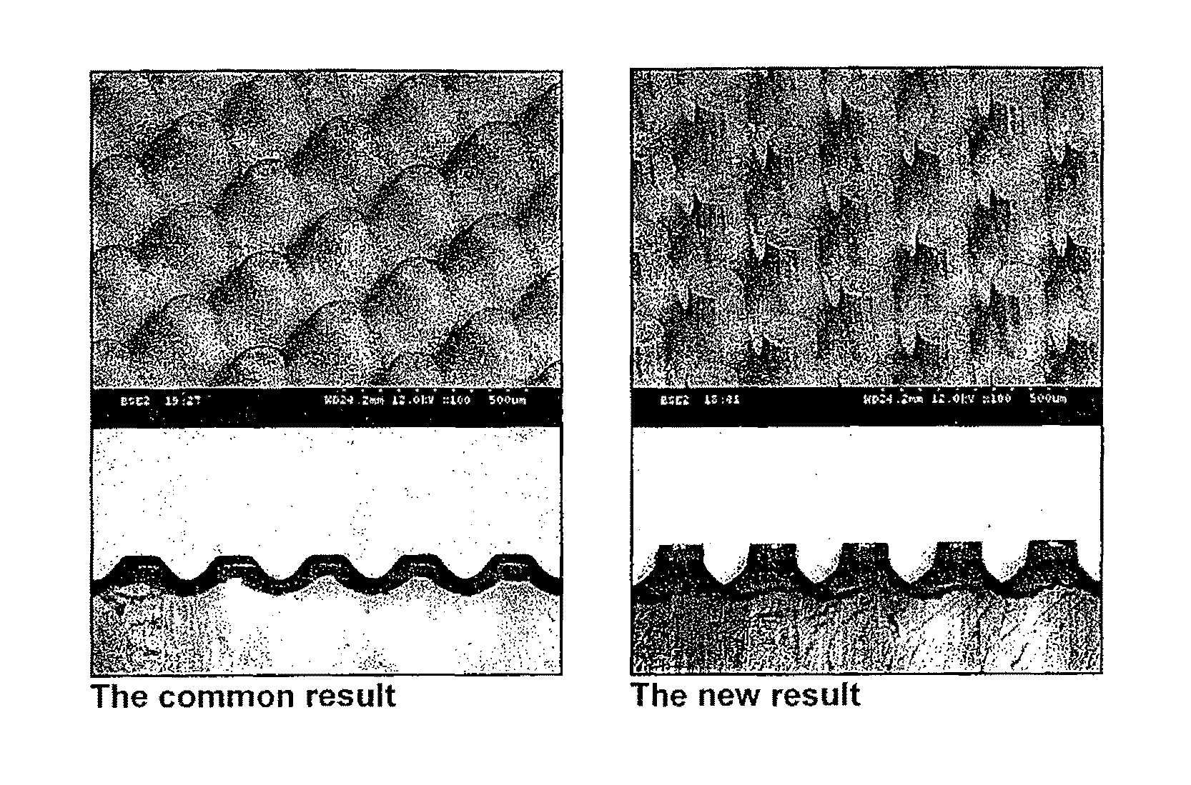
[0034]The inventors of the present invention have found that the shape and structure of a printing dot has a profound impact on the way it prints. Knowing this, one can manipulate the resultant shape of the printing dots by the methods as described herein. The use of these methods also acts to reduce the fluting tendency.

[0035]In order to reduce print fluting when printing on corrugated board substrates, the inventors of the present invention have found that it is necessary to (1) remove air from the exposure step; and preferably (2) alter the type, power and incident angle of illumination.

[0036]The use of these methods together yields a dot shape that is highly resistant to print fluting and shows exceptional impression latitude on press (i.e., resistance to print gain changes when more pressure is applied to the plate during printing).

[0037]The inventors herein have discovered that the most important method of beneficially changing the shape of printing dots formed on a printing e...


PUM

PropertyMeasurementUnit
surface roughnessaaaaaaaaaa
thicknessaaaaaaaaaa
thicknessaaaaaaaaaa

Abstract

A method of making a relief image printing element from a photosensitive printing blank is provided. A photosensitive printing blank with a laser ablatable layer disposed on at least one photocurable layer is ablated with a laser to create an in situ mask. The printing blank is then exposed to at least one source of actinic radiation through the in situ mask to selectively cross link and cure portions of the photocurable layer. Diffusion of air into the at least one photocurable layer is limited during the exposing step and preferably at least one of the type, power and incident angle of illumination of the at least one source of actinic radiation is altered during the exposure step. The resulting relief image comprises a plurality of dots and a dot shape of the plurality of dots is produced that is highly resistant to print fluting for printing on corrugated board.

Description

FIELD OF THE INVENTION[0001]The present invention relates generally to a method of preparing a relief image flexographic printing element to provide an improved relief structure thereon.BACKGROUND OF THE INVENTION[0002]Flexography is a method of printing that is commonly used for high-volume runs. Flexography is employed for printing on a variety of substrates such as paper, paperboard stock, corrugated board, films, foils and laminates. Newspapers and grocery bags are prominent examples. Coarse surfaces and stretch films can be economically printed only by means of flexography. Flexographic printing plates are relief plates with image elements raised above open areas. Generally, the plate is somewhat soft, and flexible enough to wrap around a printing cylinder, and durable enough to print over a million copies. Such plates offer a number of advantages to the printer, based chiefly on their durability and the ease with which they can be made.[0003]Corrugated board generally includes...

Claims


Application Information

Patent Timeline
Patent Type & Authority Patents(United States)
IPC IPC(8): G03F7/11B41N1/06G03F7/26
CPCG03F7/202G03F7/092
Inventor RECCHIA, DAVID A.
Owner MACDERMID PRINTING SOLUTIONS
Why Eureka
Try Eureka