Focus detection apparatus, focus detection method, and image sensing apparatus

a focus detection and focus detection technology, applied in the direction of instruments, printers, camera focusing arrangement, etc., can solve the problems of difficult to maintain the agreement of photosensitivity characteristics, difficult to calculate the focusing accuracy of the image generated, and the difficulty of each light-receiving area of the photoelectric converter to achieve the effect of improving the focusing accuracy and simple calculations

Inactive Publication Date: 2012-04-17
CANON KK
View PDF16 Cites 23 Cited by
  • Summary
  • Abstract
  • Description
  • Claims
  • Application Information

AI Technical Summary

Benefits of technology

[0010]The present invention has been made in consideration of the above situation, and has as its object to enable restoring images by simple calculations according to vignetting state of a luminous flux and thereby improve focusing accuracy.

Problems solved by technology

However, in detecting focus state by dividing the photoelectric converter of each pixel into two light-receiving areas, since vignetting is caused in the luminous flux by a lens frame of the photographing lens and the like, it is difficult for each light-receiving area of the photoelectric converter to maintain photosensitivity characteristics.
Consequently, it is difficult to maintain agreement of photosensitivity characteristics, that is, agreement in blur shape between a pair of images.
Thus, there is poor agreement between an image generated by a luminous flux passing through a first region of a pupil of the photographing lens and an image generated by a luminous flux passing through a second region different from the first region.
Consequently, the inventions disclosed in Japanese Patent Laid-Open Nos. 58-24105 and 2005-106994 have a problem in that accurate focus detection is not possible on peripheries of the photographic screen if correlation calculation is performed based on two images generated by luminous fluxes passing through different regions on the pupil of the photographing lens.
However, since it is necessary to perform convolution integration for each defocus amount, the method requires massive amounts of calculation.
Thus, the method has a problem in that it is difficult to ensure low costs and space savings when implementing the convolution integration in a realizable arithmetic processing circuit.

Method used


Image

  • Focus detection apparatus, focus detection method, and image sensing apparatus
  • Focus detection apparatus, focus detection method, and image sensing apparatus
  • Focus detection apparatus, focus detection method, and image sensing apparatus

Examples


first embodiment

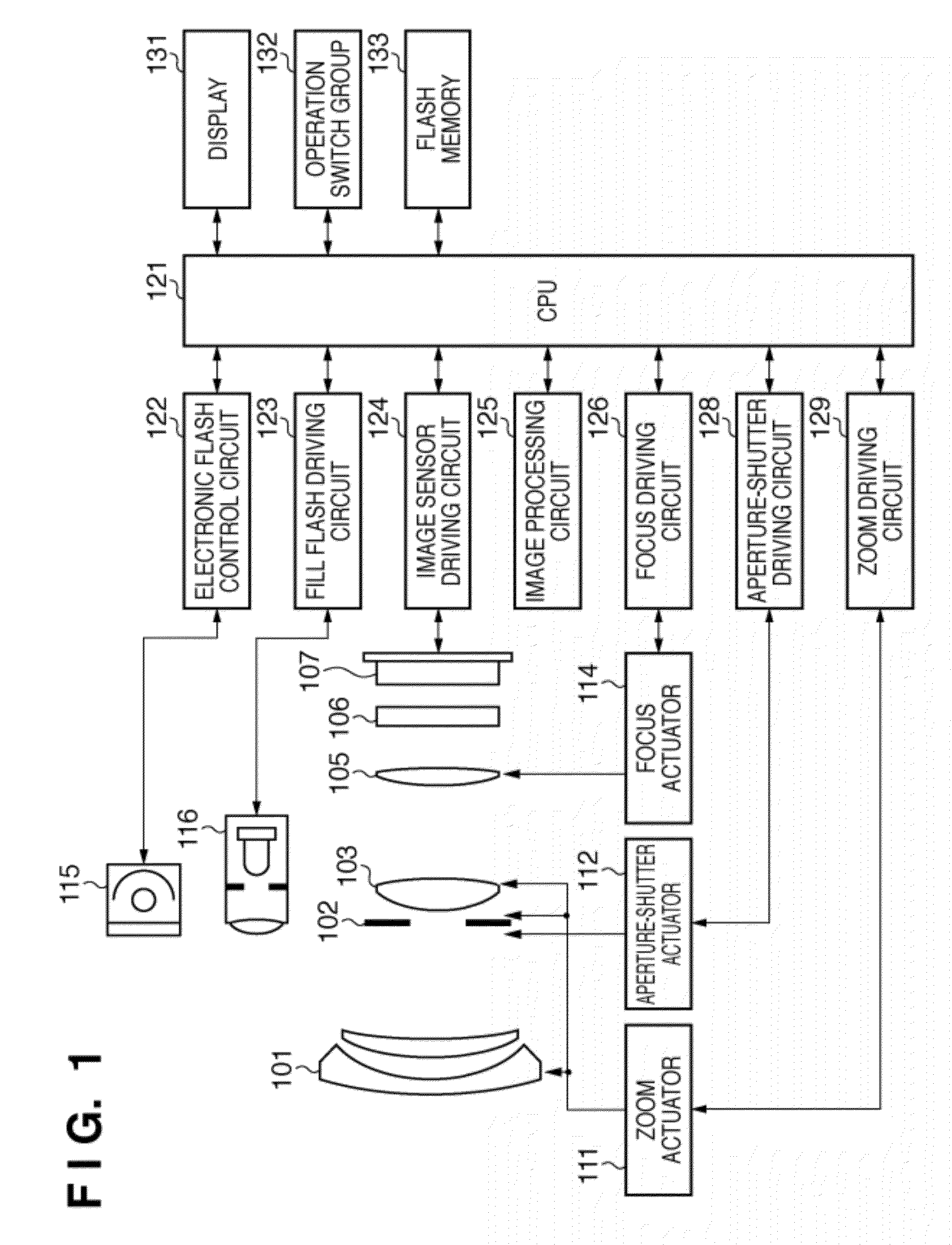
[0061]FIG. 1 is a block diagram of an image sensing apparatus according to a first embodiment of the present invention, showing an electronic camera made up of a camera body containing an image sensor, and a photographic optical system integral with the camera body. In FIG. 1, reference numeral 101 denotes a first lens group placed at the distal end of the photographic optical system (imaging optical system), being held in such a way as to be able to move forward and backward along an optical axis. Reference numeral 102 denotes an aperture-shutter which has capabilities to adjust an amount of light during shooting through adjustment of an aperture diameter and adjust exposure time (in fractions of a second) during still image shooting. Reference numeral 103 denotes a second lens group. The aperture-shutter 102 and second lens group 103 move forward and backward integrally along an optical axis, and performs a scaling operation (zoom function) in conjunction with forward and backward...

second embodiment

[0194]Next, a second embodiment of the present invention will be described.

[0195]A configuration of the image sensing apparatus according to the second embodiment is the same as the first embodiment, and thus description thereof will be omitted herein. Operation of the second embodiment will be described assuming that the aperture value of the lens (f-number) is set to 4. Pupil intensity distributions of the focus detection pixels are also similar to those of the first embodiment shown in FIGS. 14A and 14B.

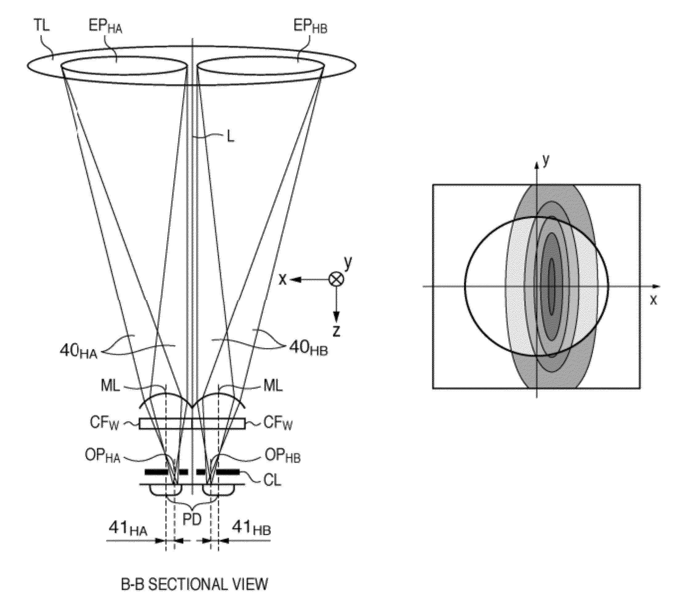
[0196]FIGS. 38A and 38B are diagrams each showing vignetting, at a predetermined aperture value (f-number) of 4, on the pupil surface Me of a focus detection pixel at the center image height Img0 of the image sensor 107, where FIG. 38A shows characteristics of the pixel SHA and FIG. 38B shows characteristics of the pixel SHB. In this case, shape of pupil vignetting corresponds to aperture size at f4, where the luminous flux passing through the shape represented by Area1 in FIG. 13...


PUM


Abstract

A focus detection apparatus includes an image sensor which includes a pair of pixel groups, outputs a first image signal from one of the pair of pixel groups, and outputs a second image signal from the other of the pair of pixel groups, where the pair of pixel groups receive luminous fluxes passing different pupil regions of an imaging optical system which forms an object image; a calculation unit which generates a first corrected image signal by subtracting the second image signal multiplied by a coefficient from the first image signal and generates a second corrected image signal by subtracting the first image signal multiplied by a coefficient from the second image signal; and a focus detection unit which detects a defocus amount based on a phase difference between the first corrected image signal and the second corrected image signal generated by the calculation unit.

Description

BACKGROUND OF THE INVENTION[0001]1. Field of the Invention[0002]The present invention relates to a focus detection apparatus, focus detection method, and image sensing apparatus, and more particularly, to a focus detection apparatus and focus detection method used in an image sensing apparatus, such as a digital still camera, capable of detecting a focus state of a photographing lens based on an image obtained from an image sensor for image sensing.[0003]2. Description of the Related Art[0004]Regarding systems for detecting a focus state of a photographing lens in a digital camera which photographs using an image sensor, an apparatus which performs pupil division-based focus detection using a two-dimensional sensor is disclosed in Japanese Patent Laid-Open No. 58-24105 (p. 2, FIG. 1), where the two-dimensional sensor has a microlens formed in each pixel. In the apparatus disclosed in Japanese Patent Laid-Open No. 58-24105, a photoelectric converter in each pixel of the image sensor ...

Claims


Application Information

Patent Timeline
Patent Type & Authority Patents(United States)
IPC IPC(8): H04N5/232G03B3/10
CPCG02B7/28H04N5/23212H04N23/672H04N25/134
Inventor TAKAMIYA, MAKOTO
Owner CANON KK
Why Eureka
Try Eureka