Heat exchange system with two single closed loops

a heat exchange system and closed loop technology, applied in the direction of heat exchange fuel, stationary tubular conduit assembly, other heat production devices, etc., can solve the problems of loss of heat pump cannot perform both heating and cooling duties at maximum efficiency, and lose efficiency in this design, etc., to achieve optimal performance efficiency, good and unique combination, and efficiency loss

Inactive Publication Date: 2012-04-24
THERMODYNAMIQUE SOLUTIONS
View PDF11 Cites 4 Cited by
  • Summary
  • Abstract
  • Description
  • Claims
  • Application Information

AI Technical Summary

Benefits of technology

[0019]The invention was conceived when it become clear that it will be ideal to split a single refrigerant loop into two separated loops connected in a cascade manner. The focus was to find a solution to solve the efficiency loss when the pressure ratio between low pressure side versus high pressure side is higher than 5. The combination of refrigerants is the key, since it is possible to use many kinds of refrigerants in combination and the system will work, but not at optimal performance efficiency. The combination of R-410a and R-134a is a very good and unique combination because many other refrigerants will be phased out in the future. R-410a and R-134a have been chosen in accordance with Montreal protocol regarding global warming. This combination is the solution to get the optimal compression ratio on both loops with temperature ranges of −10° C. to 60° C. Note that the lower temperature of −10° C. has been chosen to reduce the ground surface contact versus standard geothermal heat pumps. The gradient ground exchange is twice better than the standard heat pump system. This advantage gives the opportunity to reduce the number of drill holes, thus reducing cost for drilling. Another advantage of this system is to bring hot water to the final temperature. No space heater is needed to complete the heating cycle as the standard heat pump. This advantage gives more free energy from ground in the water heating application. Thirty percent of annual electricity consumption is for water heating. The result is that heat pump system costs 60% less than other geothermal heat pumps and gives 12% more money back than all other heat pump systems.
[0020]This invention has two main elements: (i) staging of heat exchange using the most ideal refrigerants to get maximum efficiency from work effected on these refrigerants and (ii) using the latent energy contained within the earth or warm waste water. The earth is a huge heat battery that is charged by the sun; 46% of all heat trapped by the earth is attributable to the sun. If ideal conditions exist, this heat is trapped within the earth and can easily be recaptured by the present invention. For example, ideal conditions include earth with high moisture content, since water has an excellent heat retention capacity. Sand is one of the least ideal conditions, since it dissipates stored heat very quickly after sunsets. The heat pump staging method could be use to supply hot water in the most popular heating system as radiant floor heat system, or for a hot water heating system. Warm wastewater is one of most common energy wastes in industry. The dairy, brewery, hospital laundry and juice industry use a lot of natural gas for heating water that will serve for washing applications or sterilization as pasteurization. The recuperation of this energy waste will help to reduce the global warming effect.

Problems solved by technology

This is an efficient but very costly system.
There is a loss of efficiency in this design considering that the heat pump cannot perform both heating and cooling duties at maximum efficiency due to the fact that latent heat and thermal capacity of a liquid (for cooling) and vapor (for heating) are different.
This high overlap temperature result in efficiency losses from compressors and significantly affects the total efficiency of the bolt loop staged.
The combination of refrigerants is the key, since it is possible to use many kinds of refrigerants in combination and the system will work, but not at optimal performance efficiency.
Sand is one of the least ideal conditions, since it dissipates stored heat very quickly after sunsets.

Method used


Image

  • Heat exchange system with two single closed loops
  • Heat exchange system with two single closed loops
  • Heat exchange system with two single closed loops

Examples


Embodiment Construction

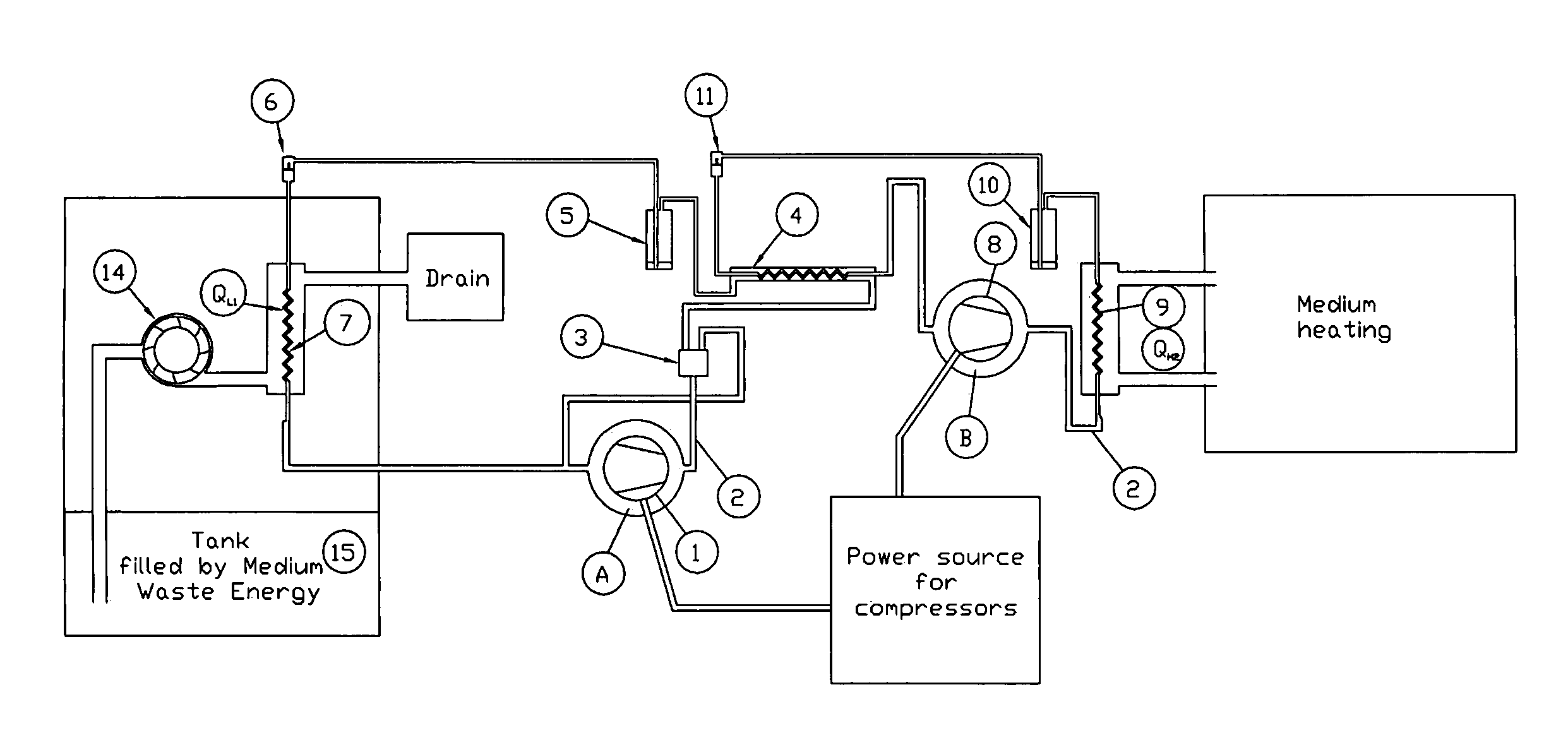
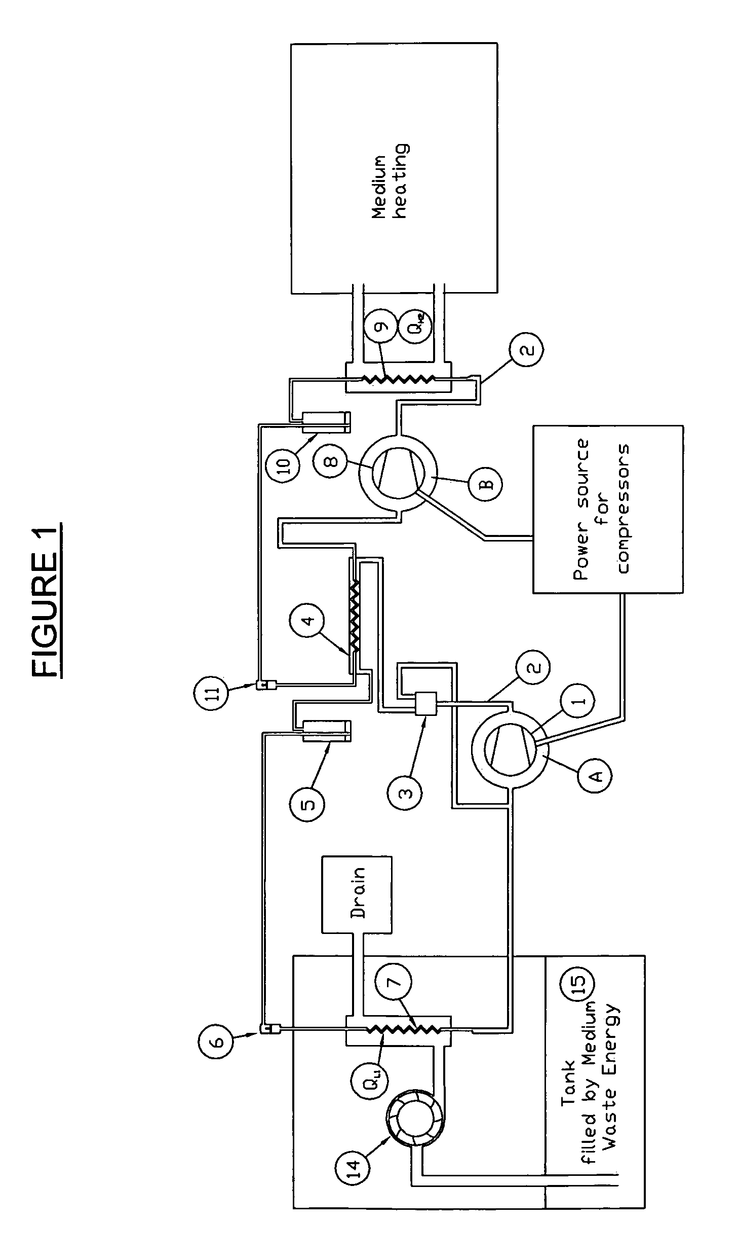
[0042]The present invention optimizes known prior art systems into a cascade of heat exchange. There are two closed loops (see FIGS. 1 and 3) that can be integrated together to yield optimal results. Referring now to FIGS. 1 and 2:

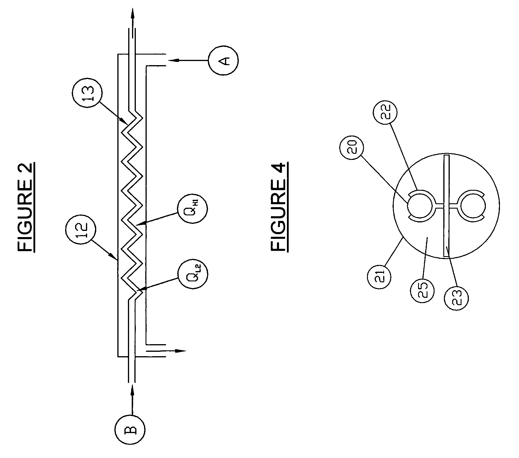
[0043]First loop comprises a copper piping system 2 filled with refrigerant A. The refrigerant A, in vapor form, is compressed by a scroll or screw compressor 1 thus turning into a liquid in the outer cylinder 12 of a transfer unit 4. Outer cylinder 12 has inlet and outlet to facilitate circulation of refrigerant A within the first loop. Refrigerant A has a condenser capacity QH1 and is provided to transfer latent heat to the refrigerant B to an inner coil 13 placed within said transfer unit 4 in coaxial manner. Inner coil 13 is provided with an inlet and outlet to facilitate circulation of refrigerant B within the second loop. Refrigerant B has an evaporator capacity QL2. A by-pass valve 3 is located between the outer cylinder 12 of transfer unit 4 and th...


PUM


Abstract

The present invention relates to a heat exchanger comprising at least one first loop adapted to trap energy from a source. The first loop contains a first refrigerant adapted to collect energy from a source. The invention also comprises at least one second loop with a second refrigerant adapted to interact with the first refrigerant and to transfer to a user a maximum quantity of the energy trapped by the first loop in the most efficient manner. The transfer of the trapped energy takes place in a transfer unit placed in the second loop. The transfer unit comprises an outer cylinder with an inlet and an outlet adapted to circulate the first refrigerant. An inner coil placed within the outer cylinder to contain the second refrigerant. The inner coil is provided with an inlet and outlet adapted to facilitate circulation of the second refrigerant. The first and the second refrigerants are moving within the transfer unit in a counter-flow direction to optimize the heat exchange between the first and second refrigerant. The first loop is placed into an earth or waste medium. The first refrigerant is R-410a and the second refrigerant is R-134a.

Description

[0001]This application is based on the Provisional Patent application US61 / 001,063, filed on Oct. 31, 2007.[0002]The present invention relates to a method and apparatus for a heat exchange system. There are known systems using refrigerants, heat exchange coils, and geothermal applications for extracting heat from the ground or warm waste water as well as staging a heat increase incrementally.[0003]The present invention comprises a system based on optimum work ranges for various known refrigerants that can be adapted for diverse environments.BACKGROUND[0004]There is known U.S. Pat. No. 4,149,585 relating to a method for transferring heat between fluids with geothermal application. This invention uses the principle of a cascading heat transfer using the same refrigerant from compressor to compressor thus increasing its temperature. This is an efficient but very costly system.[0005]There is also known U.S. Pat. No. 4,413,669 for a method of heat extraction from water through a expansio...

Claims


Application Information

Patent Timeline
Patent Type & Authority Patents(United States)
IPC IPC(8): F25D17/00
CPCF24J3/083F25B30/02F28D7/024F28F9/013F25B30/06Y02E10/125F24T10/15Y02E10/10
Inventor MAROIS, PATRICK
Owner THERMODYNAMIQUE SOLUTIONS
Why Eureka
Try Eureka