Ultrasonic medical treatment device with variable focal zone

a medical treatment device and ultrasonic technology, applied in the field of medical devices, can solve the problems of increasing the operation time and operator fatigue factor, deep heating of tissue, and requiring a much larger volume of tissue to be ablated

Inactive Publication Date: 2012-04-24
US HIFU
View PDF7 Cites 65 Cited by
  • Summary
  • Abstract
  • Description
  • Claims
  • Application Information

AI Technical Summary

Benefits of technology

[0012]A more specific object of the present invention is to provide a HIFU transducer assembly or probe that provides not only a large focal zone or treatment volume but also allows the operator to significantly expand or contract that volume at will.

Problems solved by technology

This absorption of energy causes the tissue temperature to rise, thereby causing deep heating of tissue.
However, in some cases, a much larger volume of tissue must be ablated, such an entire kidney lobe.
This has increased the operation time and operator fatigue factor considerably.
Conversely, if a transducer were constructed that provided a very large focal zone, the transducer would not be able to be used for smaller lesions or for discrete points around viable tissue or structures.

Method used


Image

  • Ultrasonic medical treatment device with variable focal zone
  • Ultrasonic medical treatment device with variable focal zone
  • Ultrasonic medical treatment device with variable focal zone

Examples


Embodiment Construction

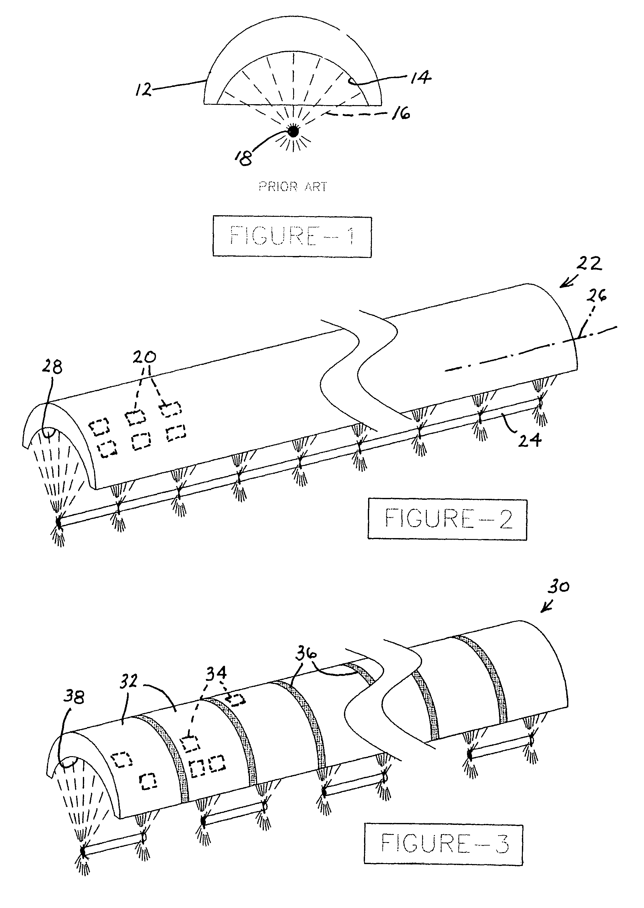
[0045]In the prior art, an ultrasonic medical treatment device has an electromechanical or electro-acoustic transducer element 10 generally in the form of a hemispherical, conical, or parabolic segment, as illustrated in FIG. 1. Energization of the transducer element 10 at ultrasonic frequencies vibrates a hemispherical, conical, or parabolic wave-generating surface 14 to thereby generate ultrasonic waves 16 in a patient's tissues. The waves 16 converge at a focal region 18 as discussed above.

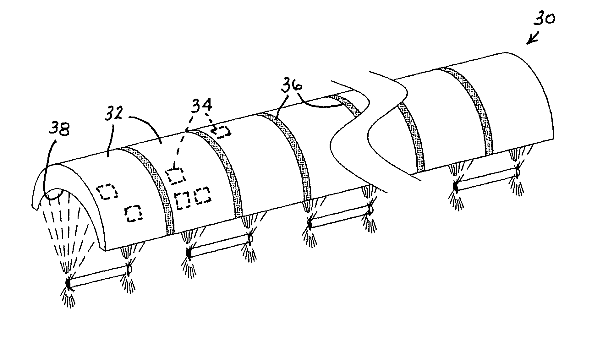
[0046]In the various embodiments of an improved high-intensity focused ultrasound (HIFU) device disclosed herein, the transducer active elements are not segments of a sphere, cone, or paraboloid of revolution 14, or disposed along a spherical, conical, or parabolic section, as in FIG. 1. Instead, as shown in FIG. 2, a probe 22 is in the form of a cylindrical section. The cylindrical section 22 may include a unitary or monolithic element such as a single piezoelectric crystal provided with an ar...


PUM


Abstract

An ultrasonic medical treatment device takes the form of an elongate probe having an elongate wave-generating concave surface with a longitudinal axis and ultrasonic electromechanical transducer elements for vibrating said concave surface to generate ultrasonic pressure waves focused along a linear locus extending parallel to said longitudinal axis. The probe may include a monolithic piezoelectric crystal element and electrode pairs provided along the unitary or monolithic element in a spaced array.

Description

CROSS-REFERENCE TO RELATED APPLICATION[0001]This application claims the benefit of U.S. Provisional Patent Application No. 60 / 635,530 filed Dec. 13, 2004.FIELD OF THE INVENTION[0002]This invention relates to a medical device and more specifically to an ultrasonic minimally or non-invasive tissue ablation instrument. Even more specifically, this invention relates to an ultrasonic medical treatment device with a variable and shaped focal zone. This invention also relates to an associated medical treatment method.BACKGROUND OF THE INVENTION[0003]In modern medicine, many forms of energy are used for their therapeutic effect. Radio-frequency electric current, microwave energy and cryogenically chilled probes are all used to ablate diseased tissue, such as cancer lesions in the body. These devices have significantly improved the treatment results over using scalpel and sutures alone.[0004]Another form of energy that has come under consideration for use as a therapeutic agent is ultrasound...

Claims


Application Information

Patent Timeline
Patent Type & Authority Patents(United States)
IPC IPC(8): A61H1/00
CPCA61N7/02A61N2007/0056A61N2007/006A61N2007/0065A61N2007/0078A61N2007/027
Inventor MANNA, RONALD R.
Owner US HIFU
Why Eureka
Try Eureka