
Printed wiring board

a printing board and wiring board technology, applied in the association of printed capacitors, printed circuit non-printed electric components, and semiconductor/solid-state device details, etc., can solve problems such as easy malfunction, achieve the effect of improving system performance, reducing power consumption, and avoiding easy malfunction

Active Publication Date: 2012-04-24
IBIDEN CO LTD
View PDF23 Cites 13 Cited by
  • Summary
  • Abstract
  • Description
  • Claims
  • Application Information

AI Technical Summary

Benefits of technology

[0004]Recently, regarding IC chips mounted on a printed wiring board, for the purpose of decreasing the power consumption and improving the system performance, microprocessors in which two or more processor cores are included in a single package, i.e. multicore processors, have been developed. When such a multicore processor is mounted on the printed wiring board disclosed in the above patent application publication, a plurality of processor cores are connected to a common layered capacitor. Therefore, when the voltage of one of the processor cores varies, the variation affects the voltages of the other processor cores, and a problem of malfunctioning easily occurs.
[0005]The present invention has been conceived in view of the above problem, and it is an object of the present invention to provide a printed wiring board on which a multicore processor is mounted and in which an instantaneous drop in the electric potential of each processor core can be suppressed, and a variation in the voltage of a processor core does not affect the other processor cores.

Problems solved by technology

Therefore, when the voltage of one of the processor cores varies, the variation affects the voltages of the other processor cores, and a problem of malfunctioning easily occurs.

Method used


Image

  • Printed wiring board
  • Printed wiring board
  • Printed wiring board

Examples


first embodiment

[0042][First Embodiment]

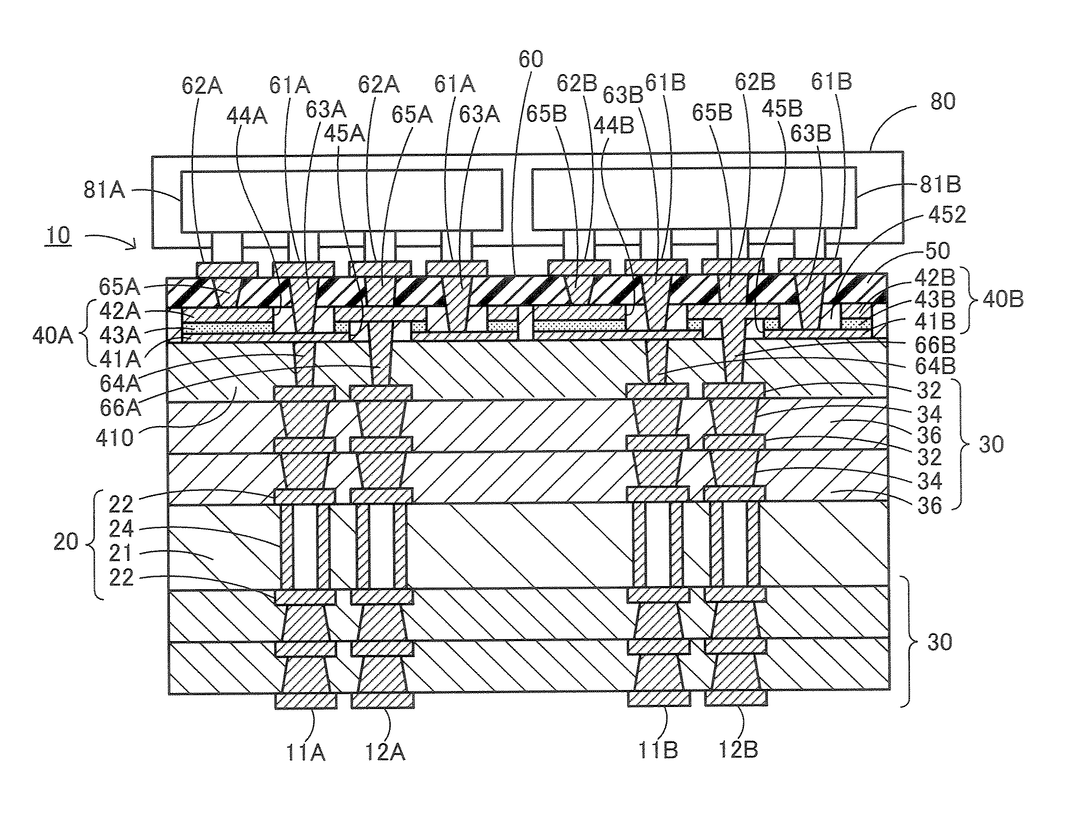
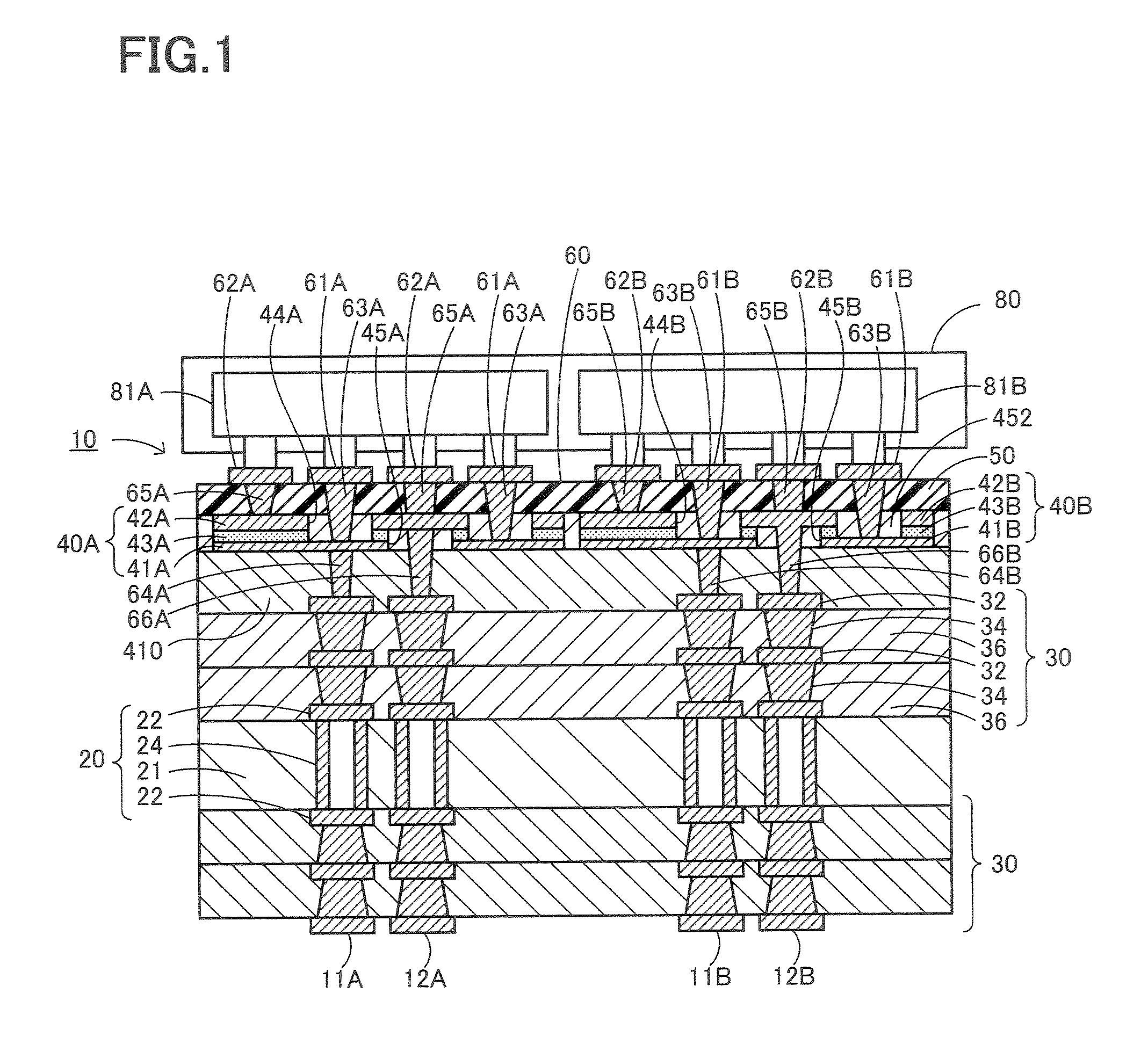
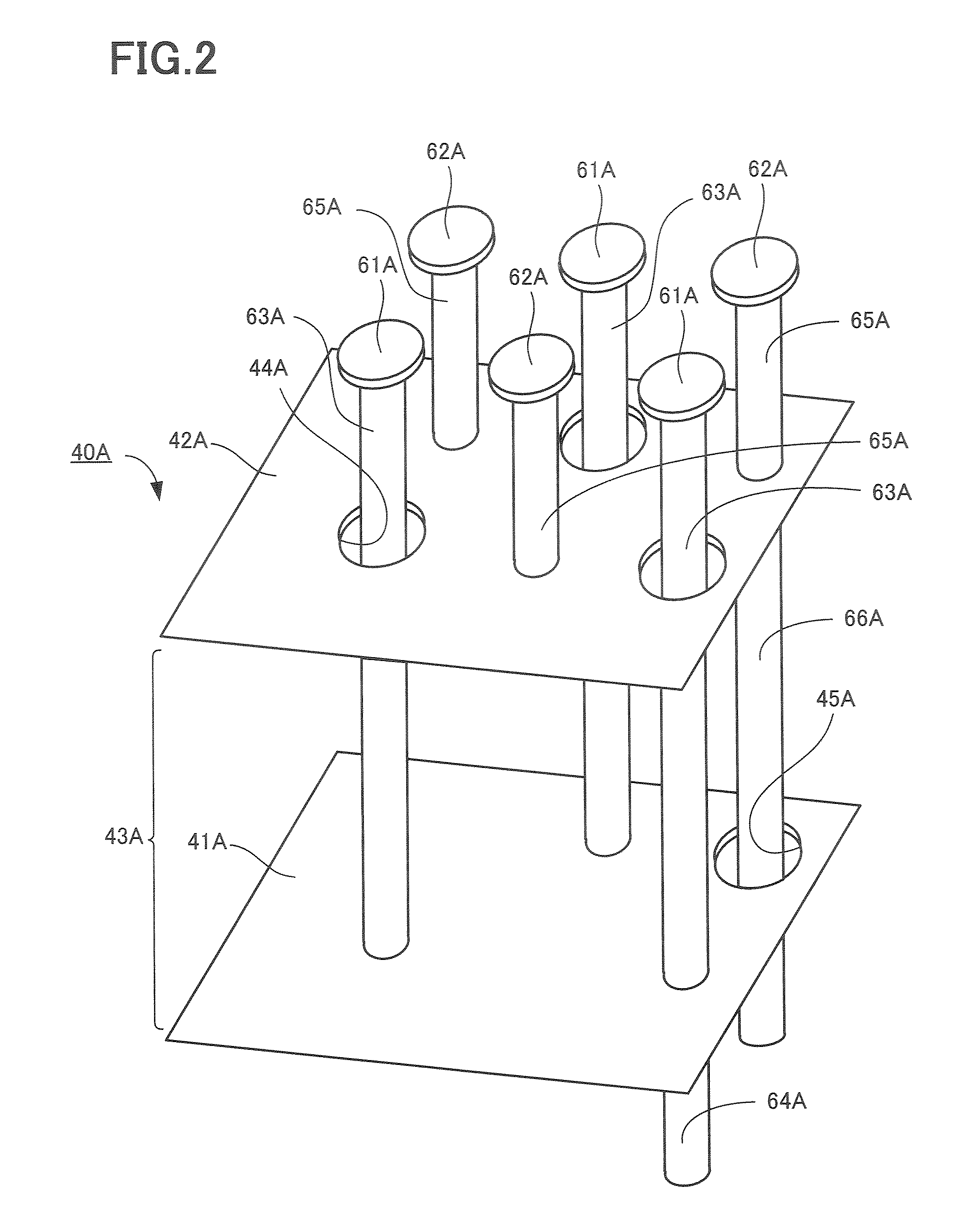
[0043]Embodiments of the present invention will now be described with reference to the drawings. FIG. 1 is a longitudinal cross-sectional view showing the overall structure of a multilayer printed wiring board 10 according to a first embodiment of the present invention. FIG. 2 is a schematic perspective view showing a first layered capacitor 40A.

[0044]The multilayer printed wiring board 10 includes a core substrate 20 in which wiring patterns 22 provided on the upper surface and the lower surface of the substrate are electrically connected to each other via through-hole conductors 24; built-up portions 30 in which a plurality of stacked wiring patterns 32 are electrically connected through resin insulating layers 36 through via holes 34, the built-up portions 30 being provided on each surface of the core substrate 20; a layered capacitor 40A which is provided on an interlayer insulating layer 410 provided on the upper surface of one of the built-up portions 3...

second embodiment

[0072][Second Embodiment]

[0073]FIG. 8 is a partial longitudinal cross-sectional view of a multilayer printed wiring board 110 according to a second embodiment. The multilayer printed wiring board 110 includes, as in the first embodiment, a mounting portion 160 on which a dual core processor 80 (see FIG. 1) including a first processor core 81A and a second processor core 81B in a single chip can be mounted, power supply lines that are independently provided for each of the processor cores, ground lines that are independently provided for each of the processor cores, and layered capacitors that are independently provided for each of the processor cores. Here, for convenience of description, a first layered capacitor 140A corresponding to the first processor core 81A will be mainly described. The structure of a second layered capacitor is substantially the same as that of the first layered capacitor 140A.

[0074]As shown in FIG. 8, the multilayer printed wiring board 110 of this embodime...

third embodiment

[0099][Third Embodiment]

[0100]FIG. 13 is a partial longitudinal cross-sectional view of a multilayer printed wiring board 210 according to a third embodiment. The multilayer printed wiring board 210 includes, as in the first embodiment, a mounting portion 260 on which a dual core processor 80 (see FIG. 1) including a first processor core 81A and a second processor core 81B in single chip can be mounted, power supply lines that are independently provided for each of the processor cores, ground lines that are independently provided for each of the processor cores, and layered capacitors that are independently provided for each of the processor cores. Here, for convenience of description, a first layered capacitor 240A corresponding to the first processor core 81A will be mainly described. The structure of a second layered capacitor is substantially the same as that of the first layered capacitor 240A.

[0101]As shown in FIG. 13, the multilayer printed wiring board 210 of this embodiment...


PUM


Abstract

A printed wiring board includes a mounting portion on which a dual core processor including two processor cores in a single chip can be mounted, power supply lines, ground lines, and a first layered capacitor and a second layered capacitor that are independently provided for each of the processor cores, respectively. Accordingly, even when the electric potentials of the processor cores instantaneously drop, an instantaneous drop of the electric potential can be suppressed by action of the layered capacitors corresponding to the processor cores, respectively. In addition, even when the voltage of one of the processor cores varies, the variation in the voltage does not affect the other processor core, and thus malfunctioning does not occur.

Description

TECHNICAL FIELD[0001]The present invention relates to a multilayer printed wiring board including a built-up portion in which a plurality of wiring patterns that are stacked with insulating layers therebetween are electrically connected through via holes provided in the insulating layers.BACKGROUND ART[0002]Hitherto, various types of structures of a printed wiring board including a built-up portion in which a plurality of wiring patterns that are stacked with insulating layers therebetween are electrically connected through via holes provided in the insulating layers have been proposed. For example, in such a printed wiring board, when a semiconductor device mounted is switched between the on and off states at a high speed, switching noise may be generated, resulting in an instantaneous drop in the electric potential of a power supply line. In order to suppress such an instantaneous drop in the electric potential, connection of a capacitor portion between the power supply line and a...

Claims


Application Information

Patent Timeline
Patent Type & Authority Patents(United States)
IPC IPC(8): H05K1/11H05K1/14
CPCH01L23/50H05K1/11H05K1/162H01L23/5384H01L24/16H01L2224/16H01L2224/81192H01L2224/81815H01L2924/0102H01L2924/01025H01L2924/01046H01L2924/01057H01L2924/01078H01L2924/01079H01L2924/14H01L2924/15311H01L2924/19041H01L2924/19043H01L2924/30105H01L2924/30107H01L2924/3011H05K1/113H05K3/4602H05K3/4652H05K2201/0175H05K2201/0355H05K2201/09309H05K2201/09509H05K2201/09518H05K2201/096H05K2201/09718H05K2201/09763H05K2201/10674H01L23/5383H01L2924/00014H01L2924/12042H01L2924/0001H01L2924/01012H01L2924/01084H01L2924/01019H01L2224/131H01L2924/014H01L2224/13099H01L2924/00H01L2224/0401H01L2924/00011H01L23/12
Inventor KARIYA, TAKASHI
Owner IBIDEN CO LTD
Learn More