Power supply with overvoltage protection by zero current stagnation detection

a technology of overvoltage protection and detection, applied in the direction of electric variable regulation, process and machine control, instruments, etc., can solve the problem of excessive output of electrical equipment, prevent excessive reduction of output electric power, and prevent excessive output of electrical equipment

Inactive Publication Date: 2012-05-01
TOYOTA JIDOSHA KK
View PDF21 Cites 6 Cited by
  • Summary
  • Abstract
  • Description
  • Claims
  • Application Information

AI Technical Summary

Benefits of technology

[0004]In a device that increases the voltage of the DC power supply with the converter and supplies the voltage to the electrical apparatus like the above described power supply device, an output voltage on a boost side sometimes becomes higher or lower than the voltage command for a short time when a direction of a current from the DC power supply changes. When the output voltage becomes lower than the voltage command, an output of the electrical apparatus becomes slightly insufficient, which causes few problems, while when the output voltage becomes higher than the voltage command, a smoothing capacitor on the boost side may be damaged to cause excessive outputs of the electrical apparatus.
[0005]A power supply device and a control method thereof according to the present invention have an object to prevent an output voltage from unexpectedly becoming higher than a voltage command. The power supply device and the control method thereof according to the present invention have another object to prevent damage to smoothing electronic equipment such as a smoothing capacitor. The power supply device and the control method thereof according to the present invention have a further object to prevent excessive outputs of an electrical apparatus that transmits electric power to and from the power supply device.

Problems solved by technology

When the output voltage becomes lower than the voltage command, an output of the electrical apparatus becomes slightly insufficient, which causes few problems, while when the output voltage becomes higher than the voltage command, a smoothing capacitor on the boost side may be damaged to cause excessive outputs of the electrical apparatus.

Method used


Image

  • Power supply with overvoltage protection by zero current stagnation detection
  • Power supply with overvoltage protection by zero current stagnation detection
  • Power supply with overvoltage protection by zero current stagnation detection

Examples


Embodiment Construction

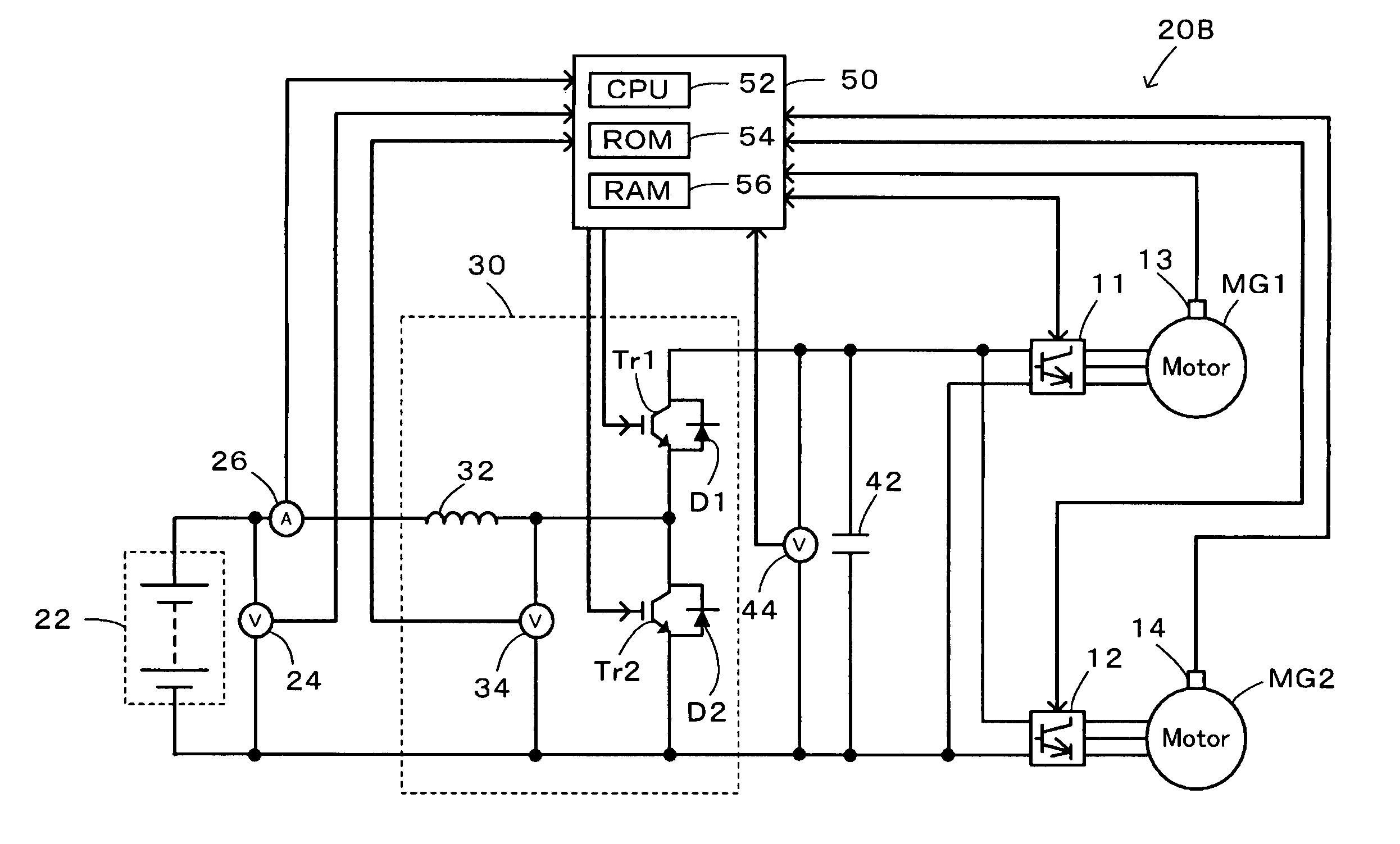
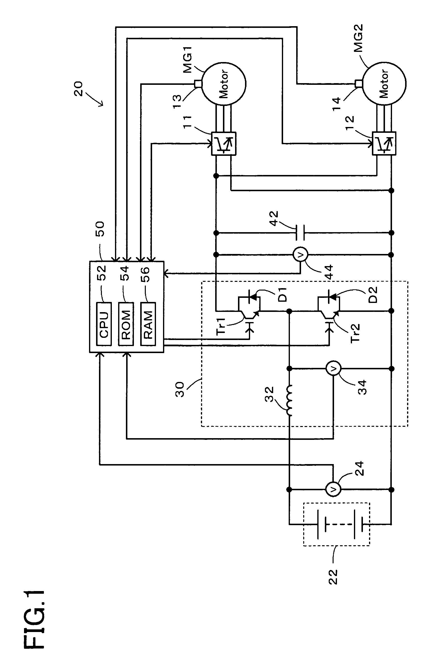
[0041]Now, the best mode for carrying out the present invention will be described with reference to an embodiment. FIG. 1 is a schematic block diagram of a configuration of a power supply device 20 according to the embodiment of the present invention. As shown, the power supply device 20 of the embodiment is connected to two motors MG1 and MG2 as electrical apparatuses via inverters 11 and 12, and includes a battery 22 as a DC power supply, a boost converter 30 that increases a voltage of the battery 22 and supplies the voltage to the two motors MG1 and MG2, or reduces a voltage of the motors MG1 and MG2 and supplies the voltage to the battery 22, a smoothing capacitor 42 that is placed on a boost side (on the side of the two motors MG1 and MG2) of the boost converter 30 and smoothes a voltage on the boost side, and an electronic control unit 50 that controls the entire device.

[0042]The battery 22 is configured as a chargeable-dischargeable secondary battery such as a lithium ion ba...


PUM


Abstract

It is determined that a periodic zero current stagnation state is reached to correct a voltage command of a smoothing capacitor downward by a predetermined voltage when a state where a current (reactor current) flowing through a coil in a dead time when switching elements are both off immediately after the switching element (upper arm) is turned off from on stagnates at a value of 0 occurs at switching periods of the switching elements. This can prevent a voltage of the smoothing capacitor from becoming unexpectedly higher than the voltage command in the current stagnation state, prevent the smoothing capacitor from being damaged by an overvoltage and prevent excessive torque from being output from motors.

Description

TECHNICAL FIELD[0001]The present invention relates to a power supply device and a control method thereof, and more particularly to a power supply device that transmits electric power to and from an electrical apparatus and a control method thereof.BACKGROUND ART[0002]A conventionally proposed power supply device of this type is such that in increasing an electric power from a DC power supply with a converter constituted by two transistors and a reactor and supplying the electric power to an electrical apparatus, an on-duty of an upper arm of the two transistors of the converter is set to 1.0 when a voltage command provided to the electrical apparatus is close to a voltage of the DC power supply (for example, see Patent Document 1). In this device, the on-duty of the upper arm is set to 1.0 when the voltage command provided to the electrical apparatus is close to the voltage of the DC power supply, thereby preventing vibration of an output voltage caused by the fact that the on-duty ...

Claims


Application Information

Patent Timeline
Patent Type & Authority Patents(United States)
IPC IPC(8): G05F1/46
CPCH02M3/1588H02M2001/385Y02B70/1466H02M1/385Y02B70/10H02M3/155H02M3/28
Inventor OKAMURA, MASAKIMATSUBARA, KIYOTAKATAMURA, SHUNGOOHTANI, HIROKINAKAI, HIDEO
Owner TOYOTA JIDOSHA KK
Why Eureka
Try Eureka