Multi-phase pulse modulation polar transmitter and method of generating a pulse modulated envelope signal carrying modulated RF signal

a multi-phase pulse and polar transmitter technology, applied in pulse combined modulation, pulse technique, pulse modulated carrier systems, etc., can solve the problems of phase data delay, phase data synchronization, and unwanted out-of-band emissions, so as to improve power amplifier efficiency, enhance bandwidth, and suppress out-of-band emissions and harmonics.

Active Publication Date: 2012-05-01
NAT TAIWAN UNIV
View PDF1 Cites 5 Cited by
  • Summary
  • Abstract
  • Description
  • Claims
  • Application Information

AI Technical Summary

Benefits of technology

[0013]Compared to the prior art, the multi-phase pulse-modulated polar transmitter of the present invention uses multi-phase pulse modulation technique and similar pulse modulation techniques, and comprises a signal modulation module that receives pulse modulation control signals and constant-envelope modulated RF input singles and perform pulse modulation on the received constant-envelope RF input signals according to the received pulse modulation control signals, to generate pulse envelopes carrying modulated RF signals. The bandwidth can be enhanced, out-of-band emissions and harmonics can be suppressed, the efficiency of a power amplifier can be improved, and an envelope path and a phase path can be easily synchronized.

Problems solved by technology

One of the major problems in implementing a Kahn EER transmitter is to synchronize the phase and envelope paths.
The non-synchronization of the phase and envelope paths may create unwanted the out-of-band emissions.
The low-pass filter, however, creates significant delay that requires the phase data to be delayed accordingly using shift registers or delay circuits.
Using the shift registers to store such data may adversely increase the area and cost of the transmitter.
However, the use of the EER method requires high quality band-pass filters to filter the unwanted out-of-band emissions created by pulse modulation or SDM noises, which hampers the wide use of the EER method.
13-17, January 2006, C. Berland, I. Hibon, J. F. Bercher, M. Villegas, D. Belot, D. Pache, and V. Le Goasccoz), but was concluded as unattractive since spurious emissions are too high.
However, unless the PWM sampling frequency is sufficiently high, the SAW filter alone is not adequate to suppress the unwanted out-of-band emissions.

Method used


Image

  • Multi-phase pulse modulation polar transmitter and method of generating a pulse modulated envelope signal carrying modulated RF signal
  • Multi-phase pulse modulation polar transmitter and method of generating a pulse modulated envelope signal carrying modulated RF signal
  • Multi-phase pulse modulation polar transmitter and method of generating a pulse modulated envelope signal carrying modulated RF signal

Examples


first embodiment

The First Embodiment

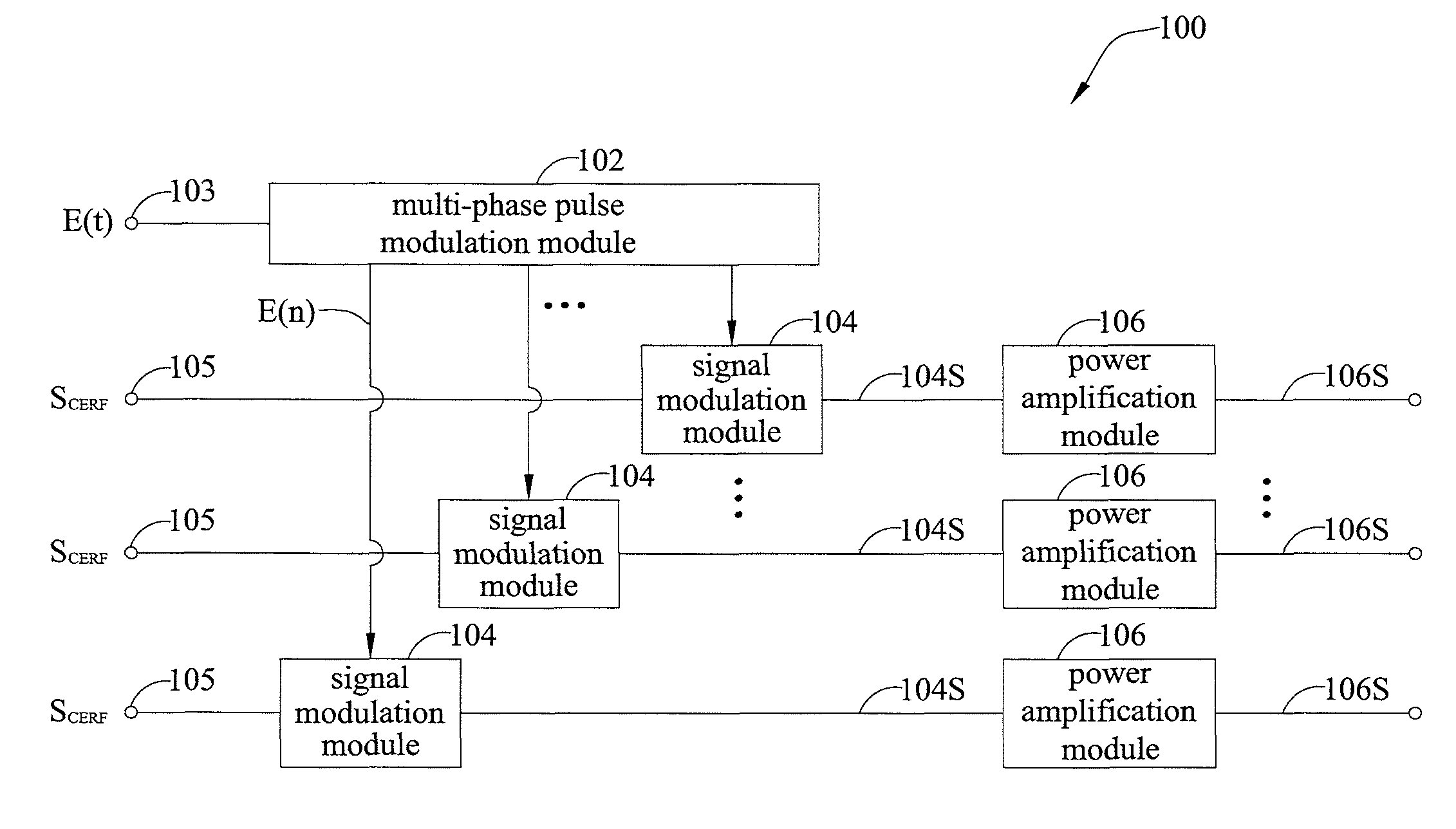
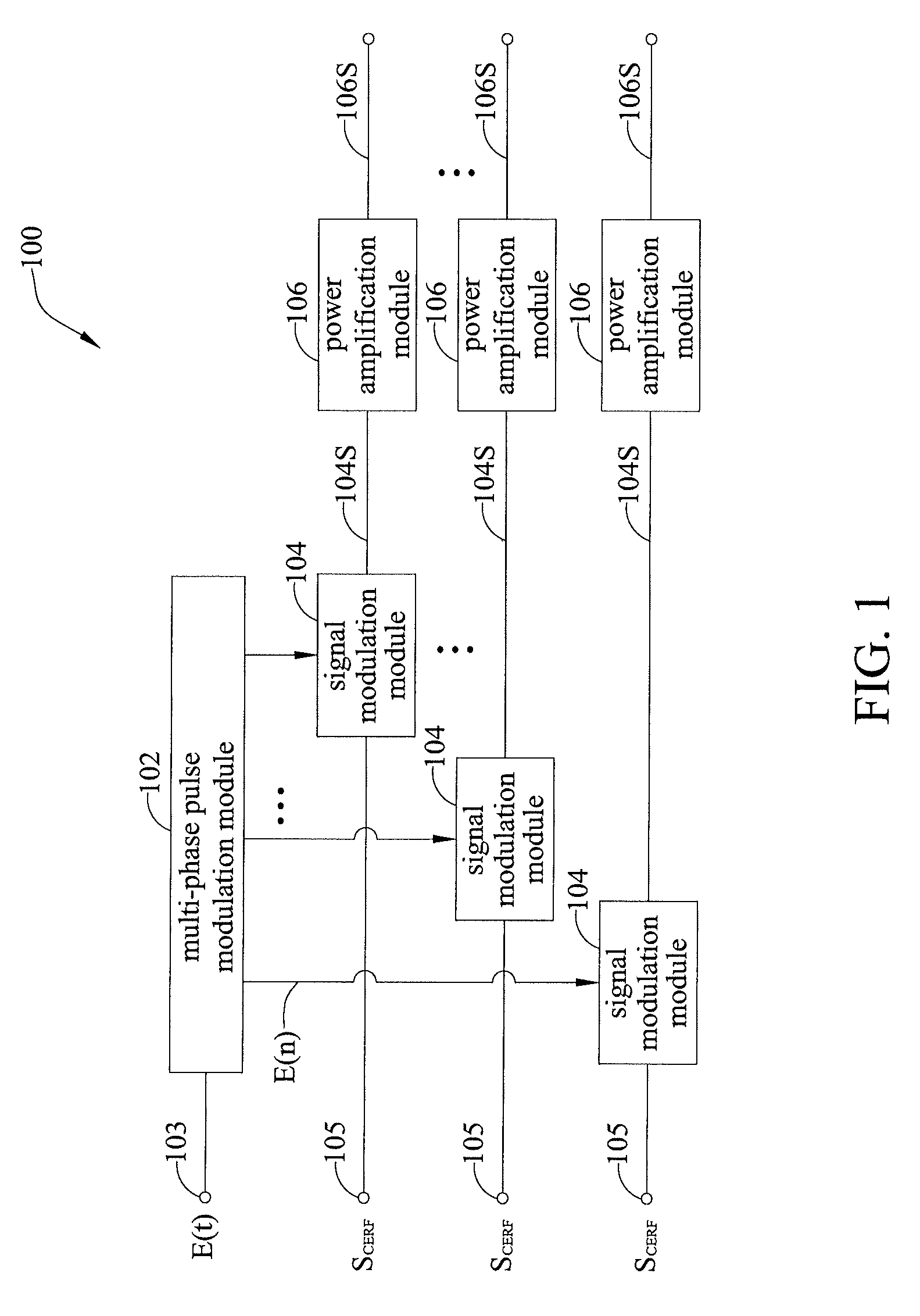
[0026]FIG. 1 is a functional block diagram of a multi-phase pulse-modulated polar transmitter 100 of a first embodiment according to the present invention. The multi-phase pulse-modulated polar transmitter 100 comprises an envelope signal input end 103, a constant-envelope RF signal input end 105, a multi-phase pulse modulation module 102, a plurality of signal modulation modules 104, and a plurality of power amplification modules 106.

[0027]The envelope signal input end 103 receives envelope signal E(t). The constant-envelope RF signal input end 105 receives one of the constant-envelope modulated RF signals SCERF.

[0028]The multi-phase pulse modulation module 102 receives the envelope signal E(t) and generates a plurality of multi-phase pulse-modulated signals E(n) that have different phases, by using a multi-phase pulse modulation technique.

[0029]The signal modulation modules 104 receive the constant-envelope modulated RF signals SCERF. Each of the signal modulat...

second embodiment

The Second Embodiment

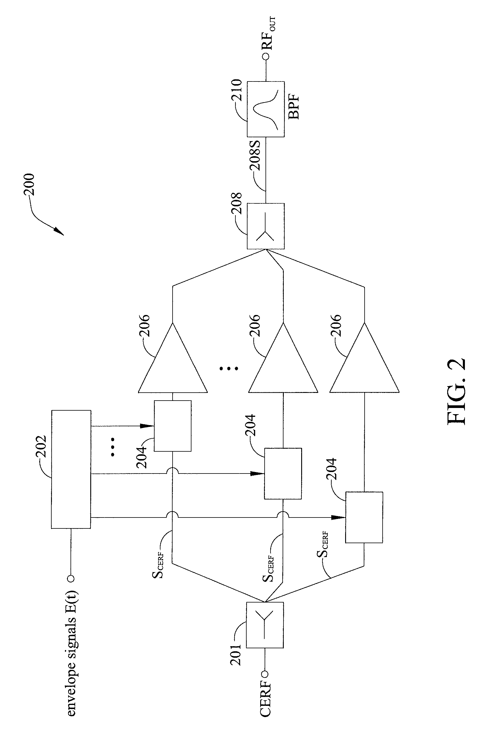
[0033]FIG. 2 is a circuit diagram of a multi-phase pulse-modulated polar transmitter 200 of the second embodiment according to the present invention. The multi-phase pulse-modulated polar transmitter 200 comprises a power divider 201, a multi-phase pulse modulator 202, a plurality of signal modulators 204, a plurality of RF power amplifiers 206, a power combiner 208 and a band-pass filter 210.

[0034]The power divider 201 receives the constant-envelope RF signal CERF of the modulated RF input signal, and divides it into a plurality of constant-envelope RF signals SCERF that may have the same or different power.

[0035]The multi-phase pulse modulator 202 receives and performs a multi-phase pulse modulation process on the envelope signal E(t) of the modulated RF input signal, and generates a plurality of multi-phase pulse-modulated signals that have different phases. The multi-phase pulse-modulated signals are then sent to the corresponding signal modulators 204. In t...

third embodiment

The Third Embodiment

[0040]A multi-phase pulse-modulated polar transmitter according to the present invention may be applied to a wireless mobile device for various standards. Please refer to FIG. 3, which describes in details a multi-phase pulse-modulated polar coordinate transmitter of the third embodiment according to the present invention.

[0041]In the third embodiment, a data generator 301 is used to generate multi-phase PWM signals E(n)″ and baseband vector signals I(n) and Q(n) directly. A plurality of signal modulation modules 304 are the same as the signal modulators 204 described in the second embodiment shown in FIG. 2. The baseband vector signals I(n) and Q(n) are two baseband vector signals that are orthogonal to each other, and are input to digital-analog converters 301a and vector modulator 301b sequentially to generate constant-envelope modulated RF signals. Each of the signal modulation modules 304 modulates the received constant-envelope RF signals carrying the phase...


PUM


Abstract

A multi-phase pulse-modulated polar transmitter and a method of generating a pulse-modulated envelope signal carrying modulated RF signal. Multi-phase pulse modulation technique or similar multi-phase pulse modulation techniques are employed in conjunction with a plurality of power amplifiers to enhance the bandwidth of the transmitter and to reduce out-of-band emissions and noises while easily synchronizing the phase and envelope of the input signal.

Description

CROSS-REFERENCES TO RELATED APPLICATIONS[0001]This application claims under 35 U.S.C. §119(a) the benefit of Taiwanese Application No. 99111917 filed Apr. 16, 2010 the entire contents of which is incorporated herein by reference.BACKGROUND OF THE INVENTION[0002]1. Field of the Invention[0003]This invention relates to using a multi-phase pulse modulation technique to implement a wideband polar transmitter, and more particularly, to a multi-phase pulse-modulated polar transmitter and a method of generating pulse-modulated envelop signals carrying modulated RF signal that may enhance the efficiency and bandwidth of a power amplifier and reduce out-of-band emissions.[0004]2. Description of Related Art[0005]In general, a power amplifier has long been known as the most power-consuming component in a radio-frequency (RF) transmitter. By improving the power amplifier efficiency, the overall battery life can be greatly increased. The envelope elimination and restoration (EER) method, which w...

Claims


Application Information

Patent Timeline
Patent Type & Authority Patents(United States)
IPC IPC(8): H03C3/00H03K7/00H03K7/10H03C3/38
CPCH03K7/08
Inventor CHEN, JAU-HORNGCHEN, YI-JAN EMERY
Owner NAT TAIWAN UNIV
Why Eureka
Try Eureka