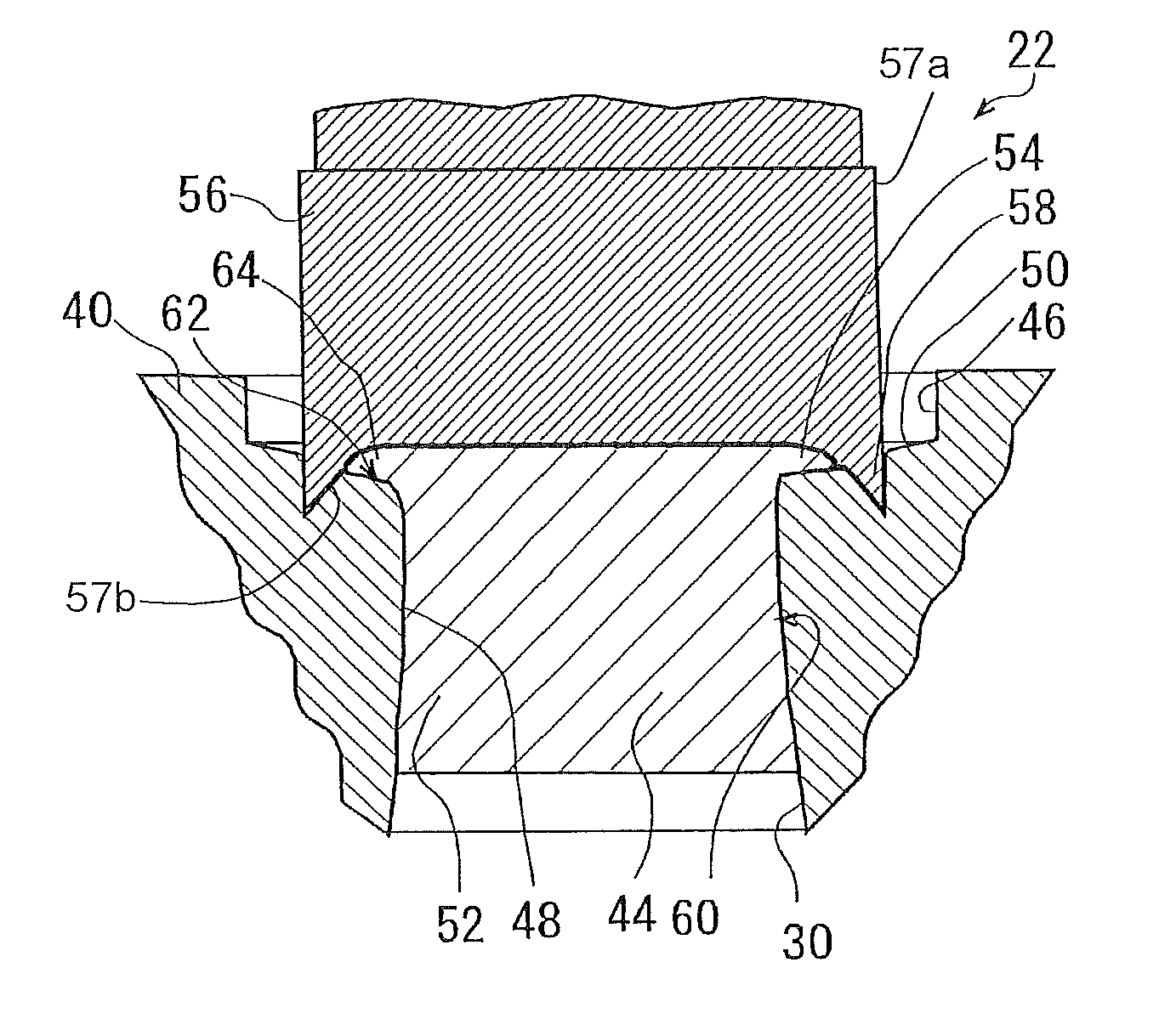
Plug structure

a technology of plugs and plugs, applied in mechanical equipment, brake systems, transportation and packaging, etc., can solve the problems of insufficient preventive power supply, increased manufacturing cost, and insufficient sealing plugs or steel balls from coming off, so as to improve the sealing or plug structure, prevent the plug or plug from coming off, and high the effect of fluid tightness

Active Publication Date: 2012-05-08
ADVICS CO LTD
View PDF9 Cites 9 Cited by
  • Summary
  • Abstract
  • Description
  • Claims
  • Application Information

AI Technical Summary

Benefits of technology

[0009]Accordingly, it is a primary object of the present invention to provide an improved sealing or plug structure for a fluid device capable of sealing, in a high quality of fluid tightness, a port formed on a fluid device to be sealed with fluid therein, so that a sealing member can reliably be prevented from coming off even if a high pressure is loaded thereon.
[0011]With this construction, at the opening end portion of the fluid passage, the part around the annular flange portion of the opening end portion is deformed to be swelled toward the annular flange portion, whereby the flange pressure-contacting portion brought into pressure contact with the lower surface of the annular flange portion is formed at the opening end portion. The circumferential edge of the annular flange portion is crushed and pressure-contacted with the flange pressure-contacting portion to form the deformed circumferential portion at the circumferential edge of the annular flange portion of the plug. Further, the circular column portion of the plug is deformed by the fluid passage which is contracted in diameter with the deformation of the part around the annular flange portion of the opening end portion, to form the contracted diameter portion of the shape made to be gradually narrow in the middle. The plug structure is provided with the flange pressure-contacting portion, the deformed circumferential portion and the contracted diameter portion and thus, constitutes a structure capable of preventing the plug from coming off the opening end portion of the fluid passage. Further, the plug and the opening end portion of the housing are plastically deformed with one on the other to realize an undividable one-piece structure in which they are adhered to each other over a wide area. Therefore, it is possible to seal the fluid passage with the fluid-tightness enhanced, and thus, the coming-off of the plug can be prevented reliably even when a high hydraulic pressure acts on the plug.
[0013]Further preferably, in a further aspect of the present invention, together with the flange pressure-contacting portion of the housing and the contracted diameter portion of the plug, the deformed circumferential portion on the annular flange portion of the plug is formed with a caulking tool which has a concave contact surface for crushing the circumferential edge of the annular flange portion and an annular peak portion formed on the circular edge of the concave contact surface for forming the annular depression on the opening end portion. Since the flange pressure-contacting portion of the housing, the contracted diameter portion of the plug and the deformed circumferential portion on the annular flange portion of the plug are formed through a single striking stroke of the caulking tool, the cost for manufacturing the plug structure can be reduced, and the manufacturing efficiency can be enhanced.

Problems solved by technology

However, in the sealing structures described in the aforementioned Japanese applications, only the circumferential edge of the opening end portion deformed by caulking serves to bear a high pressure exerted on the sealing plug or the steel ball.
Thus, it is difficult to secure the strength of the circumferential edge which is deformed by caulking at the opening end portion of the port for preventing the sealing plug or the steel ball from coming off the port, and therefore, a problem may arise in that it is insufficient to prevent the sealing plug or the steel ball from coming off due to the high hydraulic pressure acting in the fluid passage.
In addition, in the steps of forming the sealing structure, the caulking has to be done by using two kinds of punching members including the first and second punching members, and thus, there arise another problem that an increase in the manufacturing steps causes the manufacturing cost to rise.

Method used


Image

  • Plug structure
  • Plug structure
  • Plug structure

Examples


Embodiment Construction

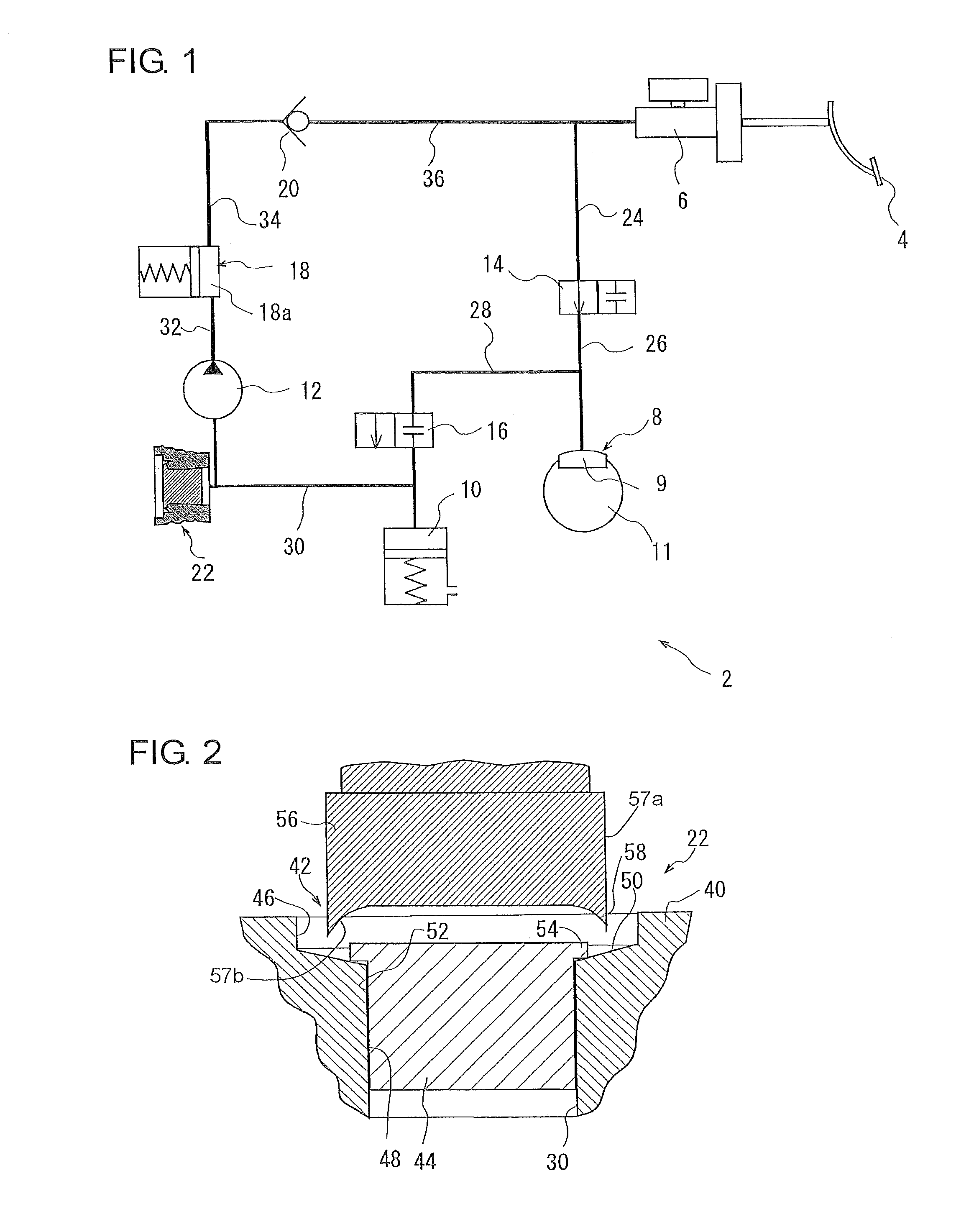
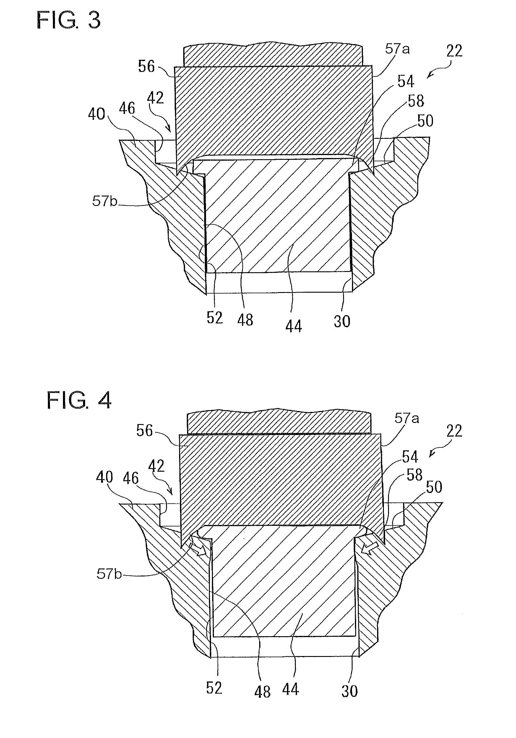
[0026]Hereafter, with reference to FIGS. 1 through 6, description will be made regarding an embodiment in which a plug device using a plug structure according to the present invention is implemented in a hydraulic circuit for a vehicle brake device. As shown in FIG. 1, the hydraulic circuit 2 for the vehicle brake device comprises a brake pedal 4, a master cylinder 6 and a brake cylinder 8 (one only shown typically for one of four road wheels of the vehicle). The hydraulic circuit further comprises an accumulation reservoir 10, a motor-driven pump 12 (which are usually common to two brake cylinders for two road wheels) and electromagnetic valves 14, 16 for the brake cylinder 8, all of which constitutes an antilock mechanism (i.e., ABS: antilock braking system) for the vehicle. Between the lower stream side of the pump 12 and the master cylinder 6, there are provided a pulse pressure damping means 18 (e.g., accumulator) and a check valve 20 both for damping the pressure pulsation in ...


PUM

PropertyMeasurementUnit
resistanceaaaaaaaaaa
diameteraaaaaaaaaa
outer diameteraaaaaaaaaa

Abstract

A plug structure for sealing an opening end portion of a circular fluid passage formed in a housing comprises a plug being equal in resistance against deformation to, or smaller than, the housing and having an annular flange portion formed on an end portion of a circular column portion; a flange pressure-contacting portion of the opening end portion deformed to be pressure-contacted with a lower surface of the annular flange portion by being caulked with a caulking tool; a contracted diameter portion of a shape gradually narrow in the middle to which the circular column portion is deformed as a result that the fluid passage is deformed by the caulking to be contracted in diameter; and a deformed circumferential portion to which the circumferential edge of the annular flange portion of the plug is deformed by the caulking to be pressure-contacted with the flange pressure-contacting portion of the opening end portion.

Description

[0001]This application is based on and claims priority under 35 U.S.C. 119 with respect to Japanese Application No. 2009-148715 filed on Jun. 23, 2009, the entire content of which is incorporated herein by reference.BACKGROUND OF THE INVENTION[0002]1. Field of the Invention[0003]The present invention relates to a plug structure for sealing a hole which is formed on a housing or the like of a fluid device sealed with fluid therein.[0004]2. Discussion of the Related Art[0005]For example, fluid devices used in the field of this related art include a brake system with a hydraulic circuit for a motor car and the like and also include a plunger pump used as a hydraulic pressure source for an accessory system such as antiskid system, power steering system or the like. In a plunger pump described in JP9-209941 A, there is shown a structure that a sealing plug is press-fitted in a port formed on a housing and that the circumferential edge of an opening end portion of the port is caulked to p...

Claims


Application Information

Patent Timeline
Patent Type & Authority Patents(United States)
IPC IPC(8): F16L55/11
CPCF16L55/11Y10T29/49938B60T7/042B60T13/146B60T13/662B60T13/686B60T8/3675B60T8/368
Inventor KOYAMA, FUMITOSHI
Owner ADVICS CO LTD
Why Eureka
Try Eureka