Method and apparatus for forming hole

a technology of forming method and hole, which is applied in the field of method and hole forming apparatus, can solve the problems of large processing load of punch, easy buckling of punch, easy rupture of punch, etc., and achieve the reduction of tensile stress, buckling and rupture of punch, and the effect of processing load on the punch while the punch is pressed into the workpi

Active Publication Date: 2012-05-08
DENSO CORP
View PDF11 Cites 2 Cited by
  • Summary
  • Abstract
  • Description
  • Claims
  • Application Information

AI Technical Summary

Benefits of technology

[0010]Since the pilot hole is formed before the punching, a processing load exerted to the punch while the punch is pressed into the work piece is reduced. Also, a tensile stress exerted to the punch while the punch is removed from the work piece is reduced. As such, buckling and rupture of the punch will be reduced.
[0011]In the directing of the laser beam, the pilot hole having a first surface condition is formed. In the punching, the finished hole is formed by transforming the first surface condition into a second surface condition that has a precise dimension. Therefore, processing accuracy and the quality of hole improve.
[0012]Further, the laser working and the punching achieve productivity higher than an electric discharge working. Therefore, the hole having sufficient processing quality is formed at high productivity.
[0014]Since the punch is operated to form a finished hole over the pilot hole, a processing load exerted to the punch while the punch is pressed into the work piece is reduced. Also, a tensile stress exerted to the punch while the punch is removed from the work piece is reduced. As such, buckling and rupture of the punch will be reduced.
[0015]The pilot hole having a first surface condition is formed by the laser head. The punch is capable of transforming the first surface condition into a second surface condition that has a precise dimension. Therefore, processing accuracy and the quality of hole improve.
[0016]Further, the laser working and the punching achieve productivity higher than an electric discharge working. Therefore, high productivity and improvement of the quality are achieved.

Problems solved by technology

In general, a punch receives a large processing load when being pressed into a work piece for punching.
The thin and long punch will be easily bucked under a large processing load when being pressed into the work piece.
Also, the thin and long punch will be easily ruptured due to a tensile stress when being removed from the work piece.
Thus, it is difficult to form the hole having the relationship of L / D≧2 by punching.
However, the electric discharge working takes a long time to form the hole, resulting in deterioration of productivity and an increase in manufacturing costs.
However, dimensional accuracy is deteriorated and an inner surface of the hole is generally rough, as compared with the electric discharge working.
Therefore, it is difficult to achieve sufficient processing quality.

Method used


Image

  • Method and apparatus for forming hole
  • Method and apparatus for forming hole
  • Method and apparatus for forming hole

Examples


Embodiment Construction

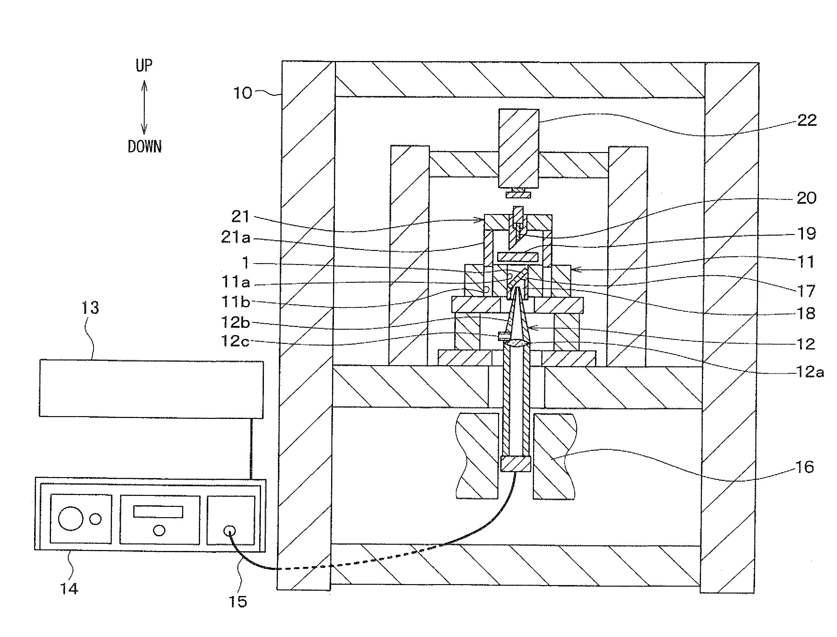
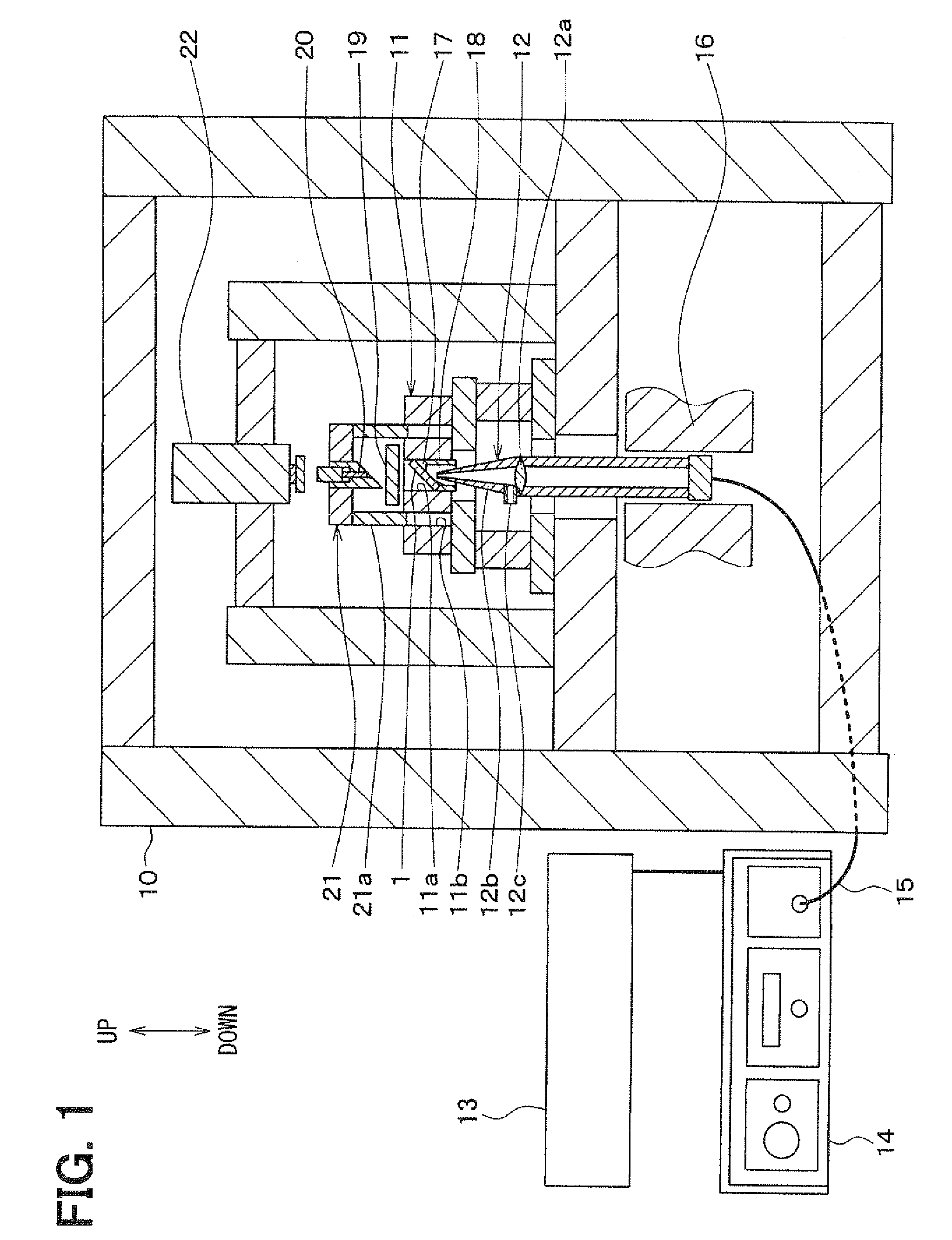
[0027]An embodiment of the present invention will now be described with reference to FIGS. 1 through 6C. Referring to FIG. 1, a working apparatus of the present embodiment is employed to work a hole in a work piece 1. The working apparatus is, for example, employed to form an injection hole of a fuel injection nozzle. In FIG. 1, an up and down arrow denotes a direction in a condition that the working apparatus is arranged.

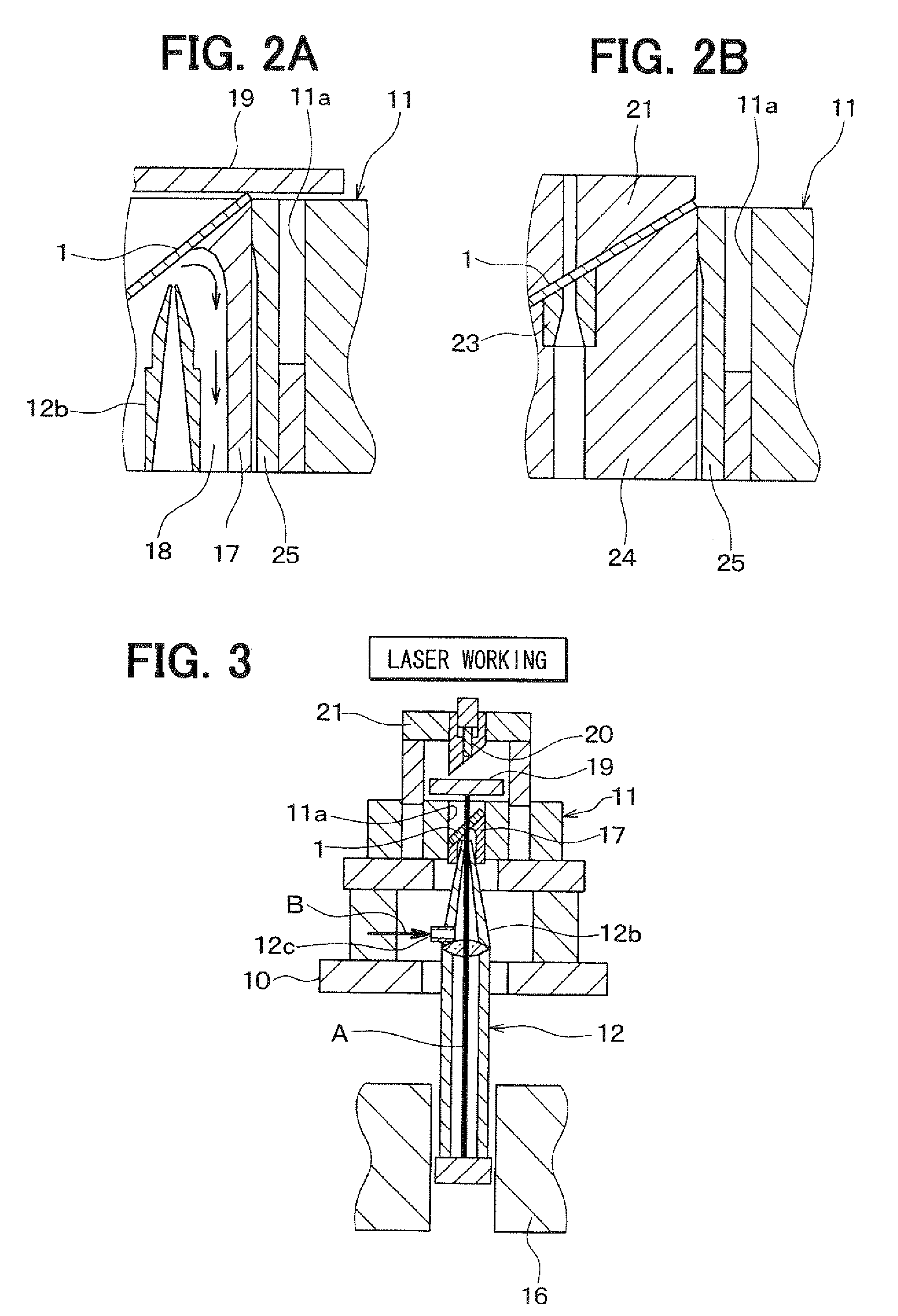
[0028]The working apparatus generally includes a laser working unit for performing laser working and a punching unit for performing punching. The laser working unit and the punching unit are configured to be movable with respect to the work piece 1, so that the laser working and the punching are performed while holding the work piece 1 at a predetermined position. That is, the working apparatus is capable of switching a laser working condition for performing the laser working and a punching condition for performing the punching without moving the work piece 1.

[0029...


PUM

PropertyMeasurementUnit
lengthaaaaaaaaaa
lengthaaaaaaaaaa
outer diameter d2aaaaaaaaaa

Abstract

In a method of forming a hole on a work piece, a laser beam is directed from a laser head to a predetermined portion of the work piece to form a pilot hole having a first surface condition, and then the predetermined portion of the work piece is punched using a die and a punch having a cross-section greater than a cross-section of the pilot hole. Thus, a finished hole having a cross-section greater than the cross-section of the pilot hole is formed over the pilot hole. The finished hole has a second surface condition, and the second surface condition is formed by transforming the first surface condition by the punch to have a precise dimension.

Description

CROSS REFERENCE TO RELATED APPLICATION[0001]This application is based on Japanese Patent Application No. 2007-221124 filed on Aug. 28, 2007, the disclosure of which is incorporated herein by referenceFIELD OF THE INVENTION[0002]The present invention relates to a method and an apparatus for forming a hole, such as an injection hole of a fuel injection nozzle.BACKGROUND OF THE INVENTION[0003]Punching using a die and a punch is conventionally known as a method of forming holes with high quality and at high productivity. For example, Japanese Unexamined Patent Application Publication No. 2002-102977 (U.S. Pat. No. 6,678,955) describes an apparatus and a method of forming an injection hole of a fuel injection nozzle by punching. Electrical discharge working and laser beam working are also generally known as methods of forming holes.[0004]In general, a punch receives a large processing load when being pressed into a work piece for punching. If the work piece is elastically deformed and ex...

Claims


Application Information

Patent Timeline
Patent Type & Authority Patents(United States)
IPC IPC(8): B23K26/00B26D1/00B21D28/24
CPCB21D28/32B23K26/388B23K26/389Y10T83/9416
Inventor TAKESHITA, KENGOHOSHIYAMA, TAKASHI
Owner DENSO CORP
Why Eureka
Try Eureka