Battery module

a battery module and battery technology, applied in the field of battery systems, can solve the problems of affecting the difficulty of monitoring the voltage of the battery module under the overall high voltage of the main battery, and the increase of the cos

Inactive Publication Date: 2012-05-08
KK TOSHIBA
View PDF9 Cites 45 Cited by
  • Summary
  • Abstract
  • Description
  • Claims
  • Application Information

AI Technical Summary

Benefits of technology

[0010]Moreover, each of the power storage device described in Japanese Patent Application Laid-open Publication No. 2003-70179 and the battery protection IC described in Japanese Patent Application Laid-open Publication No. 2005-117780 uses a semiconductor device which is designed to operate with voltage supplied from its battery. However, a semiconductor device with a high breakdown voltage has to be used as the semiconductor device used for the higher-voltage battery modules among the plural battery modules connected to one another in series. This pushes up costs.
[0011]An object of the present invention is to provide a battery system which allows a semiconductor device with a low breakdown voltage to be used therein.
[0013]In the case of the battery system according to the present invention, the first switch element is provided between the positive electrode of the highest-potential single cell in the high-potential battery module and the negative electrode of the lowest-potential single cell in the low-potential battery module. Therefore, it suffices if the first switch element has a breakdown voltage which is almost twice as high as the total sum voltage obtained by summing up the voltages respectively of all the single cells in one battery module. This allows semiconductor devices with a low breakdown voltage to be used in the battery system.

Problems solved by technology

This makes it difficult to monitor the voltage of each battery module under the overall high voltage of the main battery.
This pushes up costs.

Method used


Image

  • Battery module
  • Battery module
  • Battery module

Examples


embodiment 1

(Embodiment 1)

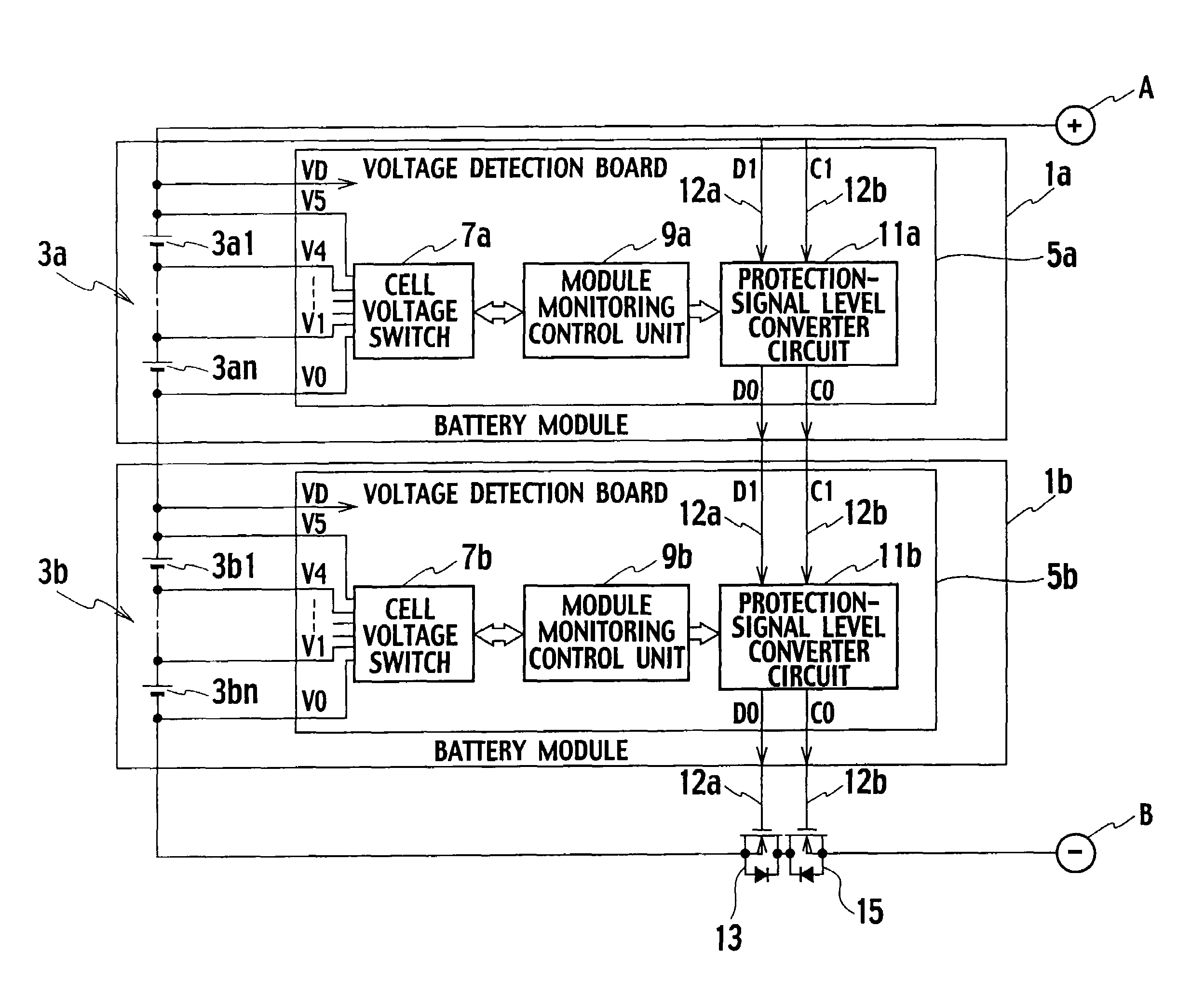
[0029]FIG. 1 is a block diagram of a configuration of a battery system according to Embodiment 1 of the present invention. The battery system shown in FIG. 1 is used, for example, as a battery for electric automobiles and the like, and is configured by connecting a battery module 1a to a battery module 1b in series. It should be noted that the battery system may be configured by connecting three or more battery modules in series.

[0030]Power from a generator (not illustrated) or regenerated power from a motor (not illustrated) is designed to be supplied between a + terminal A of the battery module 1a and a − terminal B of the battery module 1b, so that the battery modules 1a and 1b are charged. In addition, the battery modules 1a and 1b are designed to discharge by a drive of the motor.

[0031]The battery modules 1a and 1b respectively include: plural single cells 3a1 to 3an and 3b1 to 3bn connected to one another in series; cell voltage switches 7a and 7b; module monitor...

embodiment 2

(Embodiment 2)

[0046]A battery system shown in FIG. 3 includes temperature detections 21a and 21b, such as thermistors, as temperature detection units for detecting the temperatures of the plural single cells in battery modules 1a-1 and 1b-1, respectively, in addition to the configuration of the battery system according to Embodiment 1 shown in FIG. 1.

[0047]Moreover, based on information on the temperatures detected by the temperature detections 21a and 21b, module monitoring control units 9a-1 and 9b-1 output an overdischarge inhibiting protection signal and an overcharge inhibiting protection signal to the protection-signal level converter circuits 11a and 11b when the temperatures become equal to, or higher than the corresponding predetermined temperatures, respectively.

[0048]The protection-signal level converter circuit 11b outputs the overdischarge inhibiting protection signal to the discharge inhibiting switch 13, and the overcharge inhibiting protection signal to the charge in...

embodiment 3

(Embodiment 3)

[0051]FIG. 4 is a block diagram of a configuration of a battery system according to Embodiment 3 of the present invention. The battery system according to Embodiment 3 shown in FIG. 4 is characterized in that battery modules 1a-2 and 1b-2 further include discharge inhibiting switches 23a and 23b, which are connected to plural single cells 3a1 to 3an and 3b1 to 3bn, and which inhibit the plural single cells 3a1 to 3an and 3b1 to 3bn from discharging while the battery modules 1a-2 and 1b-2 are assembled with each other, respectively, in addition to the configuration of the battery system according to Embodiment 1 shown in FIG. 1.

[0052]A protection-signal level converter circuit 11b-2 outputs a discharge inhibition releasing signal, which has come from a discharge inhibition releasing switch S1, to a protection-signal level converter circuit 11a-2 and the discharge inhibiting switch 23a in the battery module 1a-2.

[0053]Based on the discharge inhibition releasing signal fr...


PUM


Abstract

In a battery system, battery modules (3a, 3b) connected to each other in series respectively include: one or more single cells (3a1 to 3an, 3b1 to 3b-n) connected to one another in any one of series, parallel, and series-parallel; cell voltage switches (7a, 7b) for detecting voltages respectively of the one or more single cells; module monitoring control units (9a, 9b) each for monitoring the detected voltages respectively of the one or more signal cells; and communications level converter circuits (14a, 14b). The battery system includes a master unit (8a) for receiving information on the voltages respectively of the one or more single cells from the module monitoring control units via the communications level converter circuits. One of the communications level converter circuits includes a switch element (Q32) for transmitting a signal of a low-potential battery module to a high-potential battery module. A series circuit includes resistors R1′, R2′ and R5 as well as the switch element is connected between a positive electrode of the highest-potential single cell in the high potential battery module and a negative electrode of the lowest-potential single cell in the low-potential battery cell.

Description

TECHNICAL FIELD[0001]The present invention relates to a battery system configured by connecting one or more battery modules in series, and particularly to a battery system configured of battery modules each including one or more single-cell lithium-ion batteries.BACKGROUND ART[0002]Electric automobiles and hybrid cars use an electric motor as a power source or an auxiliary power source. A secondary battery configured of plural single cells connected to one another in series is used as a power source for this type of electric motor. For example, Japanese Patent Application Laid-open Publication No. 2001-204141 has described a secondary battery configured of 60 nickel-metal hydride batteries with a standard voltage of 1.2 V per single cell which are connected to one another in series.[0003]In the case of such nickel-metal hydride batteries, the battery voltage of each single cell is low, and no more than approximately 70 V is obtainable even from the 60 cells connected to one another ...

Claims


Application Information

Patent Timeline
Patent Type & Authority Patents(United States)
IPC IPC(8): H02J7/00G01R31/36H02J7/02
CPCB60L3/0046B60L3/0053B60L11/1881H01M10/441H01M10/482H02J7/0021H02J7/0031H02J7/0016G01R31/3658Y02T90/34H02J2007/0037H02J2007/0039Y02T10/7055Y02T90/16G01R31/396B60L58/30H02J7/00302H02J7/00304B60L58/15B60L58/24B60L58/14Y02T10/70Y02T90/40Y02E60/10H02J7/0013H02J7/0047H02J7/00306G01R31/36
Inventor KOSUGI, SHINICHIROSHIBUYA, NOBUO
Owner KK TOSHIBA
Why Eureka
Try Eureka