Low capacitance transient voltage suppressor (TVS) with reduced clamping voltage

a transient voltage suppressor and low capacitance technology, applied in the field of integrated circuits, can solve the problems of unexpected and uncontrollable high voltage hitting the circuit, and achieve the effects of improving the clamping performance of an n+ source, low capacitance, and easy integration of steering diodes

Active Publication Date: 2013-01-03
ALPHA & OMEGA SEMICON INC
View PDF9 Cites 25 Cited by
  • Summary
  • Abstract
  • Description
  • Claims
  • Application Information

AI Technical Summary

Benefits of technology

[0022]Additionally, an isolation layer (not shown) may be formed above the second epitaxial layer 209 with openings formed therein to provide for metal contacts. A Vcc pad (not shown) may make contact to the second source region 219′ above the Zener diode through an opening in the isolation layer. An n-type sinker region 217 may be formed between the second source region 219′ and the n+ buried layer 205 to allow the Zener diode to form a connection at the top surface of the device 200. In reverse mode, the n-type sinker region 217 acts as part of a PN junction that can be used to improve the clamping performance of an N+ source to the substrate 201 both in positive and negative mode. An I/O pad (not shown) may make contact to the p+ implant region 221 (i.e., anode of high-side steering diode) through another opening in the isolatio

Problems solved by technology

However, in situations such as electrostatic discharge (ESD), electrical fast transients and ligh

Method used


Image

  • Low capacitance transient voltage suppressor (TVS) with reduced clamping voltage
  • Low capacitance transient voltage suppressor (TVS) with reduced clamping voltage
  • Low capacitance transient voltage suppressor (TVS) with reduced clamping voltage

Examples


Embodiment Construction

Introduction

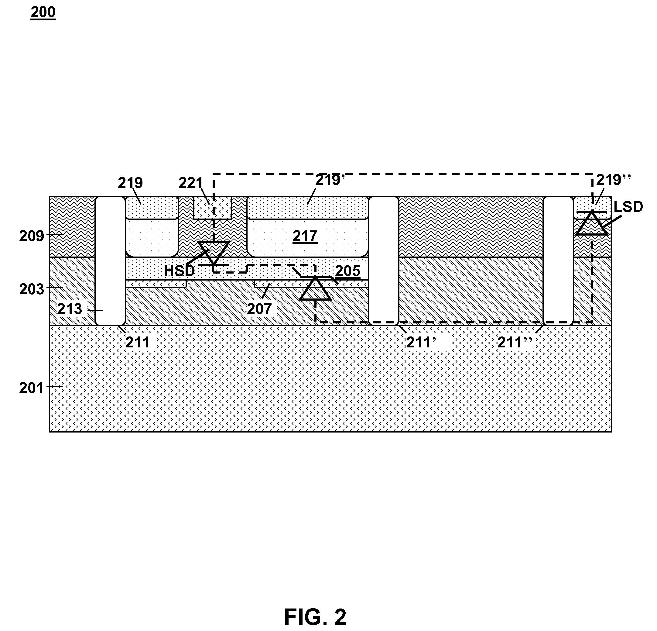
[0016]FIG. 2 is a cross-sectional schematic diagram illustrating a conventional transient voltage suppressor (TVS) device 200 in accordance with the prior art. This conventional TVS 200 behaves in accordance with the TVS 100 described above in the circuit diagram of FIG. 1.

[0017]The TVS 200 is formed on a heavily doped p+ semiconductor substrate 201 which supports a first epitaxial layer 203 and a second epitaxial layer 209. The first epitaxial layer 203 is a lightly doped p− layer. This first epitaxial layer 203 may be doped with Boron having a concentration on the order of 1015 / cm3. The second epitaxial layer 209 is a very lightly doped p− layer. This second epitaxial layer 209 may also be doped with Boron, having an even lower doping concentration on the order of 1014 / cm3 or lower. Because the doping concentration of the second epitaxial layer 209 contributes significantly to the capacitance of both the high-side steering diode HSD and low-side steering diode LSD it i...


PUM


Abstract

A low capacitance transient voltage suppressor with reduced clamping voltage includes an n+ type substrate, a first epitaxial layer on the substrate, a buried layer formed within the first epitaxial layer, a second epitaxial layer on the first epitaxial layer, and an implant layer formed within the first epitaxial layer below the buried layer. The implant layer extends beyond the buried layer. A first trench is at an edge of the buried layer and an edge of the implant layer. A second trench is at another edge of the buried layer and extends into the implant layer. A third trench is at another edge of the implant layer. Each trench is lined with a dielectric layer. A set of source regions is formed within a top surface of the second epitaxial layer. The trenches and source regions alternate. A pair of implant regions is formed in the second epitaxial layer.

Description

FIELD OF INVENTION[0001]This invention relates to integrated circuits and more specifically to a transient voltage suppressor (TVS).BACKGROUND OF INVENTION[0002]Transient voltage suppressors (TVS) are devices used to protect integrated circuits from damages caused by over voltage imposed onto the integrated circuit. An integrated circuit is designed to operate over a normal range of voltages. However, in situations such as electrostatic discharge (ESD), electrical fast transients and lightning, an unexpected and an uncontrollable high voltage may accidentally strike onto the circuit. The TVS devices are required to provide protection to circumvent the damages that are likely to occur to the integrated circuits when such over voltage conditions occur. As an increasing number of devices are implemented with integrated circuits that are vulnerable to over voltage damages, demands for TVS protection are also increased. Exemplary applications of TVS can be found in USB power and data lin...

Claims


Application Information

Patent Timeline
IPC IPC(8): H01L23/60H01L21/336
CPCH01L27/0255H01L21/265H01L29/66113H01L21/822H01L27/0248H01L21/76224
Inventor GUAN, LINGPENGBOBDE, MADHURBHALLA, ANUPHU, JUNENG, WAYNE F.
Owner ALPHA & OMEGA SEMICON INC
Why Eureka
Try Eureka