Check patentability & draft patents in minutes with Patsnap Eureka AI!

Method and circuit for avoiding hard switching in half bridge converters

a half-bridge converter and hard-to-switch technology, applied in the field of electronic devices, can solve the problems of high switching frequency, low heat generation, and high switching efficiency of half-bridge converters, and achieve the effects of avoiding hard-to-switch losses, avoiding hard-to-switch losses, and avoiding hard-to-switch losses

Active Publication Date: 2012-05-08
STMICROELECTRONICS SRL
View PDF4 Cites 4 Cited by
  • Summary
  • Abstract
  • Description
  • Claims
  • Application Information

AI Technical Summary

Benefits of technology

The solution reduces switching losses and prevents hard switching during startup, improving efficiency and reducing power wastage by ensuring symmetrical current sourcing and sinking, thus maintaining converter stability and extending component lifespan.

Problems solved by technology

Moreover, a half-bridge converter is characterized by high efficiency, and low generation of heat.
However, while operating at higher frequencies allows a considerable reduction in the size of the passive components included in a half-bridge converter—such as the transformers and the filters—, a high switching frequency entails an increase of the so-called driving losses and of the so-called switching losses.
While the driving losses are caused by the electrical power used for switching the switching elements, there are two different types of switching losses.
The switching losses become particularly noticeable in case it is necessary to provide electric charge for turning on a switching element implemented with a power MOS transistor that has a high drain to source voltage (“hard switching” condition).
The half-bridge converters are affected by a quite serious drawback occurring during the start up.
This is a disadvantageous condition, which causes an asymmetry in the current sourced / sunk by the resonant tank.
In this condition, a high peak of current is generated, which wastes a high amount of power.

Method used


Image

  • Method and circuit for avoiding hard switching in half bridge converters
  • Method and circuit for avoiding hard switching in half bridge converters
  • Method and circuit for avoiding hard switching in half bridge converters

Examples


Embodiment Construction

[0029]In the following, a solution according to exemplary and non-limitative embodiments will be presented and described in detail. Those skilled in the art will however recognize that several modifications to the described embodiments are possible, and that the present invention can be embodied in different ways.

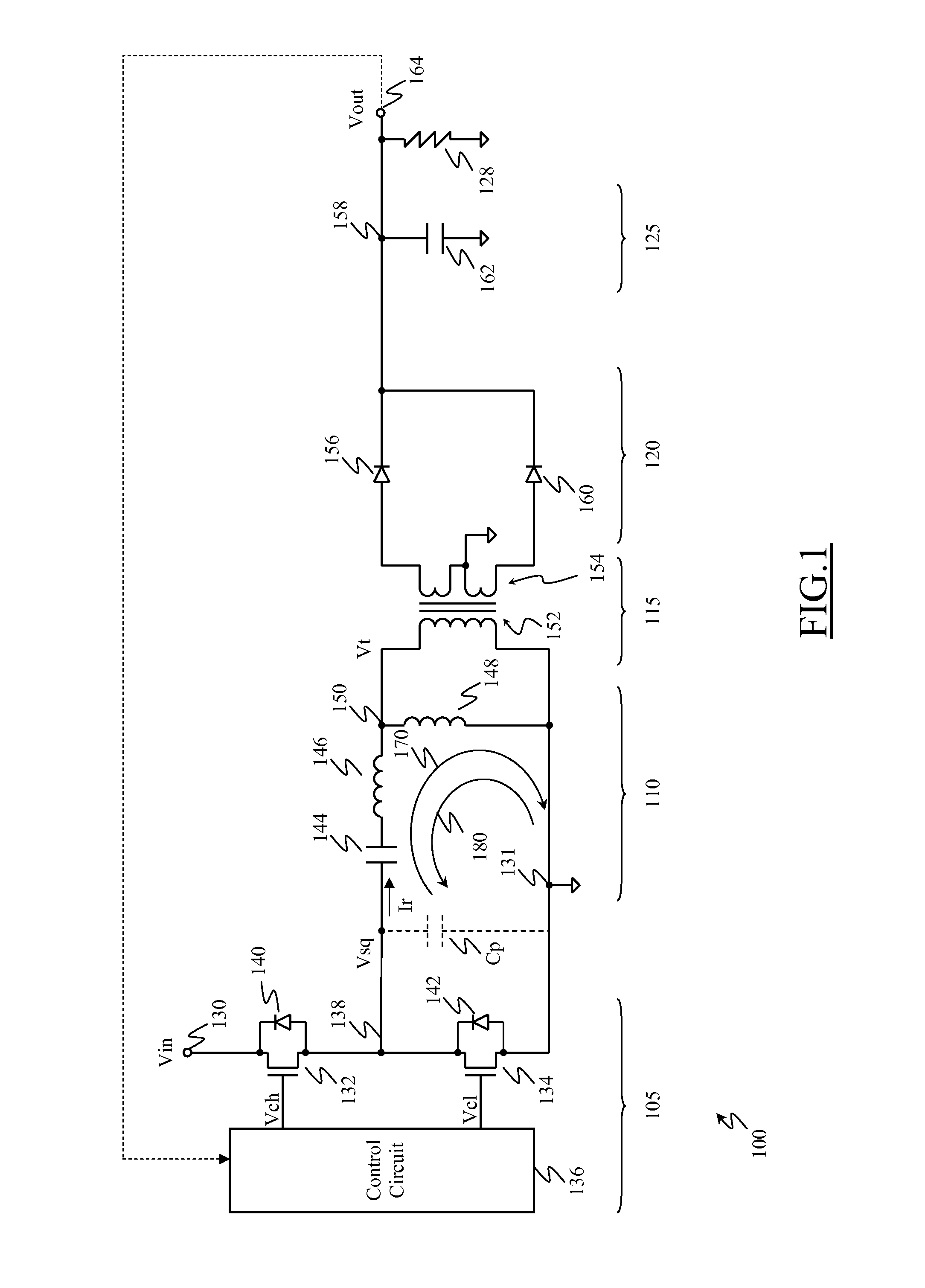
[0030]With reference in particular to FIG. 1, a switching dc-dc converter according to one embodiment is illustrated with the reference 100. The converter 100 illustrated in FIG. 1 is an LLC half-bridge converter provided with a dc blocking capacitor; however, it has to be appreciated that similar considerations apply to different topologies, including LC, LCC and plain half-bridge topologies provided with a dc blocking capacitor.

[0031]The converter 100 includes five main sections cascade connected, and particularly a square wave generator 105, an input resonant network 110, a transformer 115, a rectifier 120 and a filter 125.

[0032]The converter 100 receives an input dc vol...


PUM


Abstract

A half bridge switching dc-dc converter an input dc voltage to an output dc voltage. The converter includes a switching circuit for receiving the input dc voltage and generating a periodic square wave voltage oscillating from a high value corresponding to the input dc voltage to a low value corresponding to a reference voltage. The periodic square wave voltage oscillates at a main frequency with a main duty cycle equal to about 50% when the converter operates in a steady state. The converter further includes a conversion circuit for providing the output dc voltage from the square wave voltage based on the main frequency and on the main duty cycle. The converter still further comprises a switching control circuit controlling the switching circuit for temporarily varying the main duty cycle during at least one period of the square wave after a power on of the converter.

Description

BACKGROUND[0001]1. Technical Field[0002]The solution according to the present disclosure relates to the electronic field. Particularly, such solution concerns switching direct current-direct current (dc-dc) converters.[0003]2. Description of the Related Art[0004]In electronics, a dc-dc converter is an electronic circuit adapted to convert a dc source from a voltage value to another one. An important application field of the dc-dc converters regards the electronic systems supplied through the power grid. Particularly, such electronic systems generally comprise a supply circuit capable of generating a dc voltage by rectifying the (alternating) voltage provided by the power grid; however, a generic electronic system is typically formed by a plurality of sub-circuits, each needing a different supply voltage value. The presence of one or more dc-dc converters allows to locally generate said different supply voltage values starting from the one generated by the supply circuit.[0005]Among ...

Claims


Application Information

Patent Timeline
Patent Type & Authority Patents(United States)
IPC IPC(8): H02M3/335H02M3/24
CPCH02M3/337H02M2001/0048Y02B70/1433Y02B70/1491Y02B70/10H02M1/0048H02M3/33571H02M3/01
Inventor ADRAGNA, CLAUDIODE SIMONE, SILVIO
Owner STMICROELECTRONICS SRL
Features
  • R&D
  • Intellectual Property
  • Life Sciences
  • Materials
  • Tech Scout
  • Unparalleled Data Quality
  • Higher Quality Content
  • 60% Fewer Hallucinations
Learn More