Wireless communication apparatus for selecting suitable transfer route on wireless network

a wireless network and wireless communication technology, applied in power management, high-level techniques, frequency-division multiplexes, etc., can solve the problems of low communication efficiency, interference and collision of wireless signals, and the inability to perform upward and downward communications at the same time, so as to avoid interference and collision between wireless signals, reduce total power consumption, and balance power consumption

Active Publication Date: 2012-05-08
OKI ELECTRIC IND CO LTD
View PDF5 Cites 9 Cited by
  • Summary
  • Abstract
  • Description
  • Claims
  • Application Information

AI Technical Summary

Benefits of technology

[0016]It is an object of the present invention to provide an improved wireless communication apparatus for use in a wireless communication network. It is a more specific object of the present invention to provide a wireless communication apparatus that is capable of avoiding interference / collision between wireless signals, balancing a power consumption between communication terminals or reducing the total power consumption of a communication network, and avoiding a communication interruption due to the failure of such a terminal or disconnection of a wireless link between the terminals. It is another object of the invention to provide a method, a computer program and a wireless communication network for such a wireless communication.
[0021]According to the wireless communication apparatus of the present invention, a plurality of transfer routes are prepared in the wireless network, and therefore, the apparatus can avoid interference and collision between wireless signals, balance the power consumption among the terminals or reduce the total power consumption, and avoid a communication interruption otherwise caused by terminal failure or wireless link disconnection.

Problems solved by technology

By contrast, in wireless communications, upward and downward communications may not be frequently operated simultaneously, i.e. in a half-duplex system, and then the upward and downward communications may simultaneously take place to thus lower the efficiency of the communications.
However, when the route control scheme is adopted in a wireless multi-hop network, some problems may be caused as following.
Firstly, almost all wireless communication systems use the half-duplex communication so that the upward and downward communications cannot be performed simultaneously.
If the paths of the upward and downward communications took the same route, wireless signals could interfere and collide with each other.
Secondly, in almost all communication systems, levels required for the delay and quantity of communications are asymmetric between the upward and downward communications.
Thus, the existing route control scheme may thus fail to select an appropriate terminal.
Fourthly, the conventional route control scheme tends to cause communications to converge on a specific terminal, so that a lot of wireless signals may collide in the vicinity of such a specific terminal to thus lower the communication efficiency.
Since the terminal on which the communications converges transfers a lot of packets, it consumes more electric power consumption than other terminals.
Although the system disclosed by the above-mentioned Japanese patent publication '637 can resolve the first problem, it needs to install at least two gateway wireless stations at separate positions, thereby causing a problem of increasing the cost.

Method used


Image

  • Wireless communication apparatus for selecting suitable transfer route on wireless network
  • Wireless communication apparatus for selecting suitable transfer route on wireless network
  • Wireless communication apparatus for selecting suitable transfer route on wireless network

Examples


Embodiment Construction

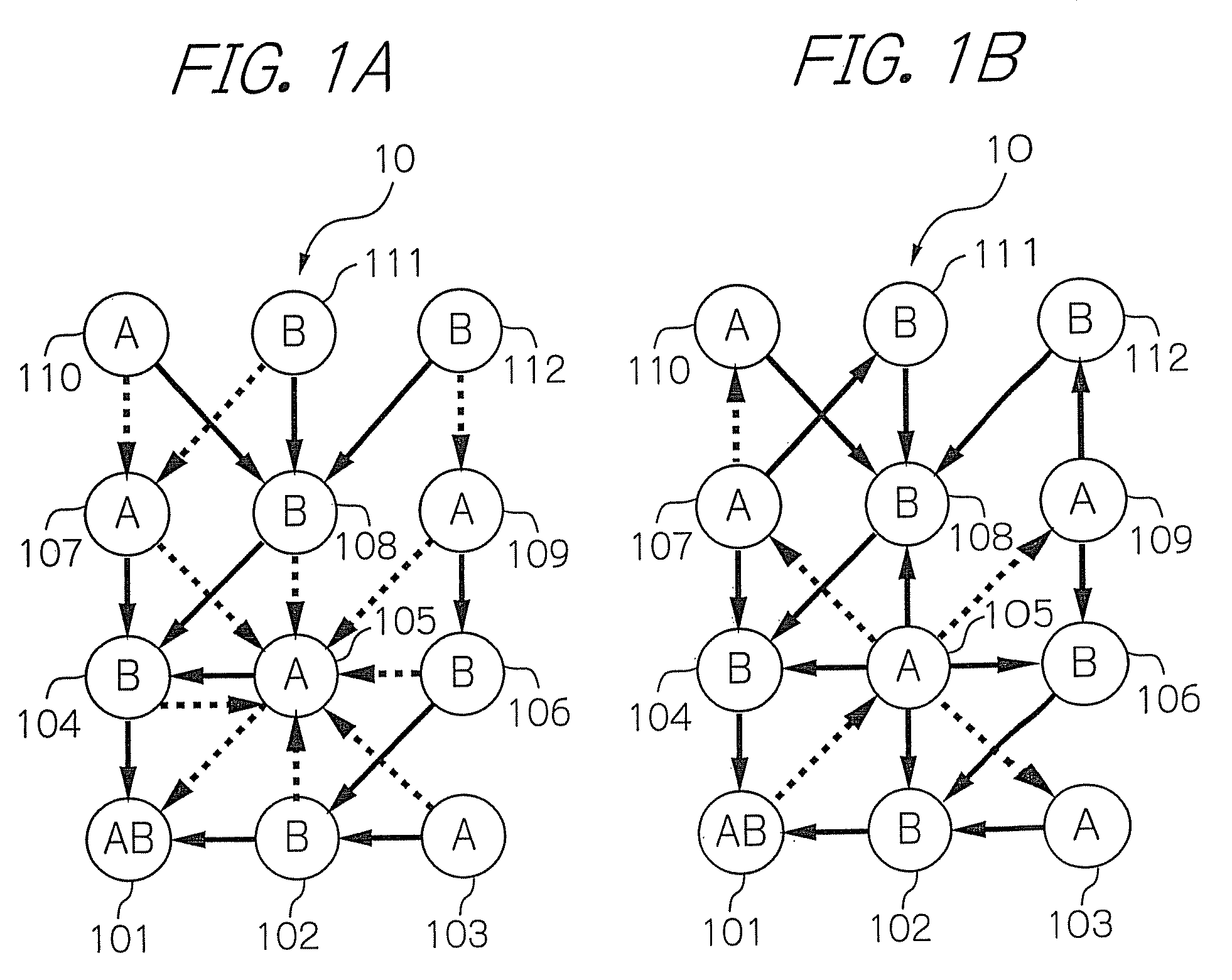
[0033]An illustrative embodiment of a wireless communication network system according to the present invention will be described in detail with reference to the accompanying drawings. In the illustrative embodiment, a wireless multi-hop network comprises a plurality of wireless communication apparatuses, i.e. wireless terminals which respectively introduce the prevent invention.

[0034]FIGS. 1A and 1B schematically show communication between the wireless terminals on the wireless multi-hop network in accordance with the illustrative embodiment. With reference to the figures, the illustrative embodiment includes a wireless multi-hop network 10 comprising a plurality of wireless terminals 101 to 112. Specifically, the wireless terminal 101 is equipped with the management function of managing the entire network, herein after being referred often to as a coordinator.

[0035]In FIGS. 1A and 1B, a solid line and a dotted line connecting two wireless terminals indicate a wireless link establis...


PUM


Abstract

A wireless communication apparatus prepared in each of wireless terminals configuring a wireless network adapted to transmit and receive a data signal and terminal information to and from peripheral wireless terminals of a subject wireless terminal; to manage the terminal information received from the peripheral wireless terminals; to determine a relay network to which the subject terminal belongs on the basis of the terminal information of the peripheral wireless terminals when the subject terminal can be connected to at least one of the relay networks provided within the wireless network; to transmit terminal information including information indicating the relay network of the subject terminal to the peripheral wireless terminal; and to use the relay network of the subject terminal as a data signal transfer route to perform forward processing. Thus, the apparatus can prepare plural transfer routes to avoid wireless signal interference and collision and balance the power consumption among the terminals.

Description

BACKGROUND OF THE INVENTION[0001]1. Field of the Invention[0002]The present invention relates to a wireless communication apparatus for selecting a suitable transfer route on a wireless network, and more specifically to such an apparatus, for setting a transfer route, for example, in a multi-hop wireless network such as a sensor network. The present invention also relates to a method and a computer program for implementing such an apparatus, as well as a wireless network for utilizing such an apparatuses.[0003]2. Description of the Background Art[0004]Conventionally, in a telecommunications network consisting of a plurality of communication terminals, various types of communication systems have been developed to communicate with other terminals not directly connected to the communication terminals by repeating transmission and receipt of packets between adjacent ones of those terminals.[0005]In addition, in the network, a relaying terminal must select appropriate one of adjacent ter...

Claims


Application Information

Patent Timeline
Patent Type & Authority Patents(United States)
IPC IPC(8): H04B7/14H04L45/02H04L45/85H04W16/26H04W40/10H04W40/14H04W40/22H04W40/26H04W52/02H04W84/12H04W84/18
CPCH04W40/24H04W52/0219H04W40/10H04W52/0274Y02B60/50Y02D30/70
Inventor YANAGIHARA, KENTAROU
Owner OKI ELECTRIC IND CO LTD
Why Eureka
Try Eureka