
Mobile fuel distribution station

Active Publication Date: 2012-05-15
CAPAT LLC
View PDF9 Cites 50 Cited by
  • Summary
  • Abstract
  • Description
  • Claims
  • Application Information

AI Technical Summary

Benefits of technology

[0011]It is another object of the present invention to provide a mobile fuel distribution station that may be easily and quickly installed in a minimum space.
[0029]It is yet another object of the present invention to provide a mobile fuel distribution station that can easily be manufactured, transported and assembled.

Problems solved by technology

The construction and operation of known fuel distribution and service stations, however, are lengthy, costly and resource-consuming undertakings.
Moreover, known fuel stations are not flexible and are not capable of providing different types of fuels for distribution.
As will be readily appreciated, the construction of known fueling stations is also not the most environmentally-friendly practice.
Indeed, the footprint of known fueling stations, in terms of both its permanence and from an environmental standpoint, is rather substantial.
Currently, fossil fuel distribution is made through permanent establishments which require public works, excavations, etc. and which have no flexibility in terms of design or configuration.
In addition, known stations require electricity from the electrical grid and cannot be relocated in an economically feasible or profitable way.
Underground installation of these tanks requires relatively large excavations and coverage thereof and creates many potential problems.
One known problem associated with underground fuel tanks is leakage or seepage into the surrounding soil.
This is particularly true of metallic tanks, which can corrode or degrade over time, especially in moist soil.
Seepage into the surrounding soil results both in the steady loss of fuel and environmental (soil and water) pollution.
Moreover, in case of flooding, the tanks installed underground are inefficient and the fuel in them may be contaminated with water and with sediments within the water.
As these tanks are buried underground beneath the structure of the station, the cost of repairing and replacing a leaking underground tank can be extremely expensive.
In addition, underground tanks are not designed to store different types of fuels, and other facilities are needed to store equipment and to perform processes needed to produce certain types of fuel and energy to deliver to automobiles.
Moreover, known fossil fuel distribution stations have very high operating costs because the fuel, stored in an underground tank, must be mechanically pumped from the tank to an automobile.
As will be readily appreciated, this mechanical pumping consumes a lot of electricity.
Accordingly, in the event that the fueling station is no longer in operation, a lengthy and expensive process of removing everything that was previously constructed (pilings, tanks, pumps, structure) must be competed to restore the land to a condition in which it can be easier to sell and / or meet zoning or land ordinances.
In many cases, once installed, such facilities cannot practically be moved to different locations, or be sold.
Known “permanent” fueling stations also suffer from additional drawbacks.
In remote areas where fuel is required, or may be required on short notice, it may not be practical to go through this lengthy and expensive planning and construction process to meet fuel demand.
In addition, due to the lack of infrastructure in many remote areas, e.g., accessibility to the energy / electricity grid, it may not even be feasible to construct known fueling stations in such areas.
In particular, the electrical energy required to operate the pumps, lights, credit card machines, etc. may simply not be readily available.

Method used


Image

  • Mobile fuel distribution station
  • Mobile fuel distribution station
  • Mobile fuel distribution station

Examples


Embodiment Construction

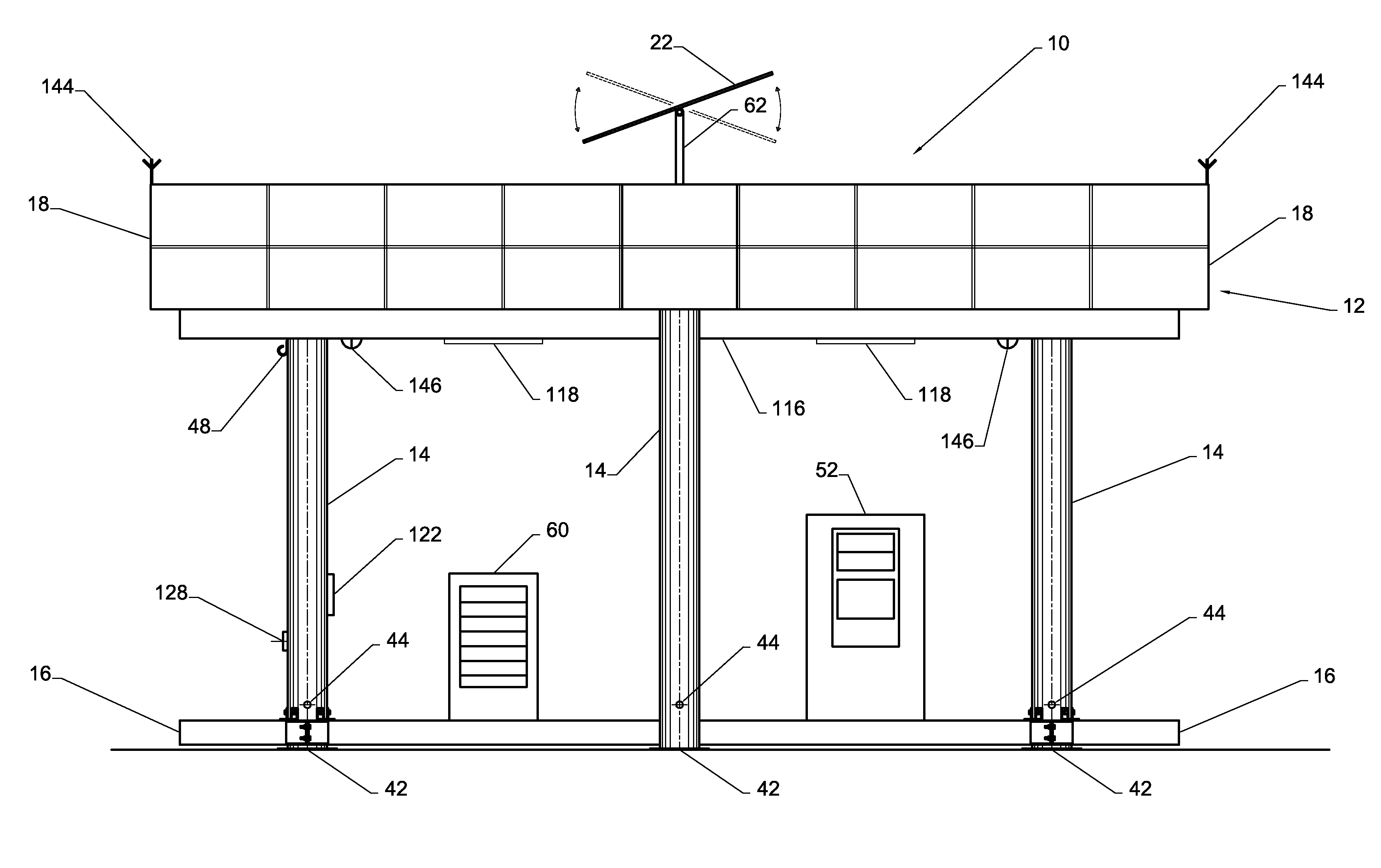
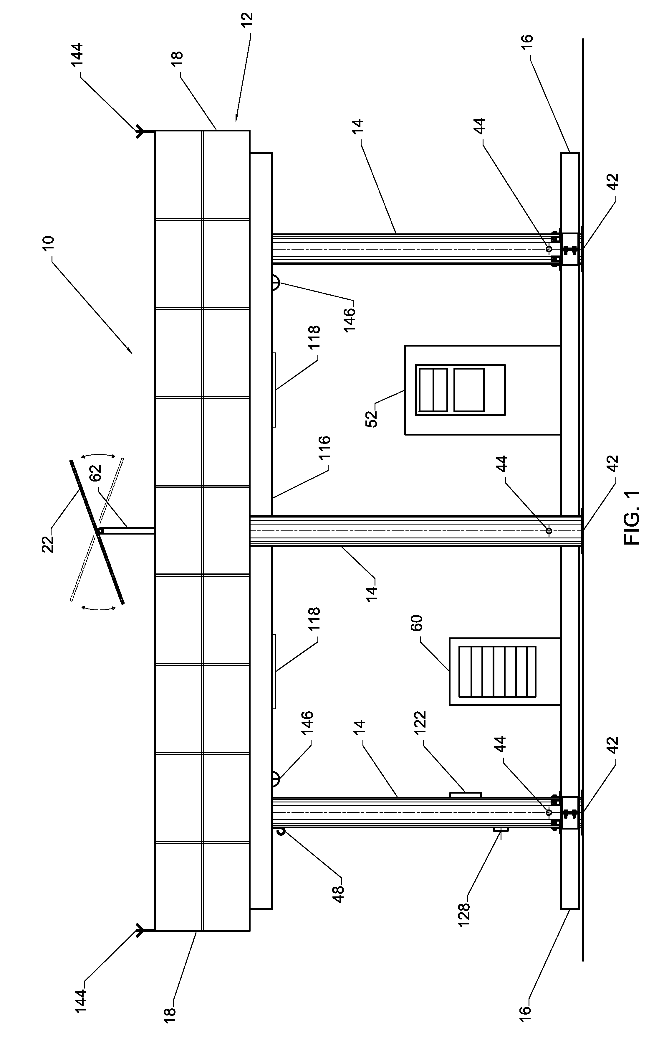
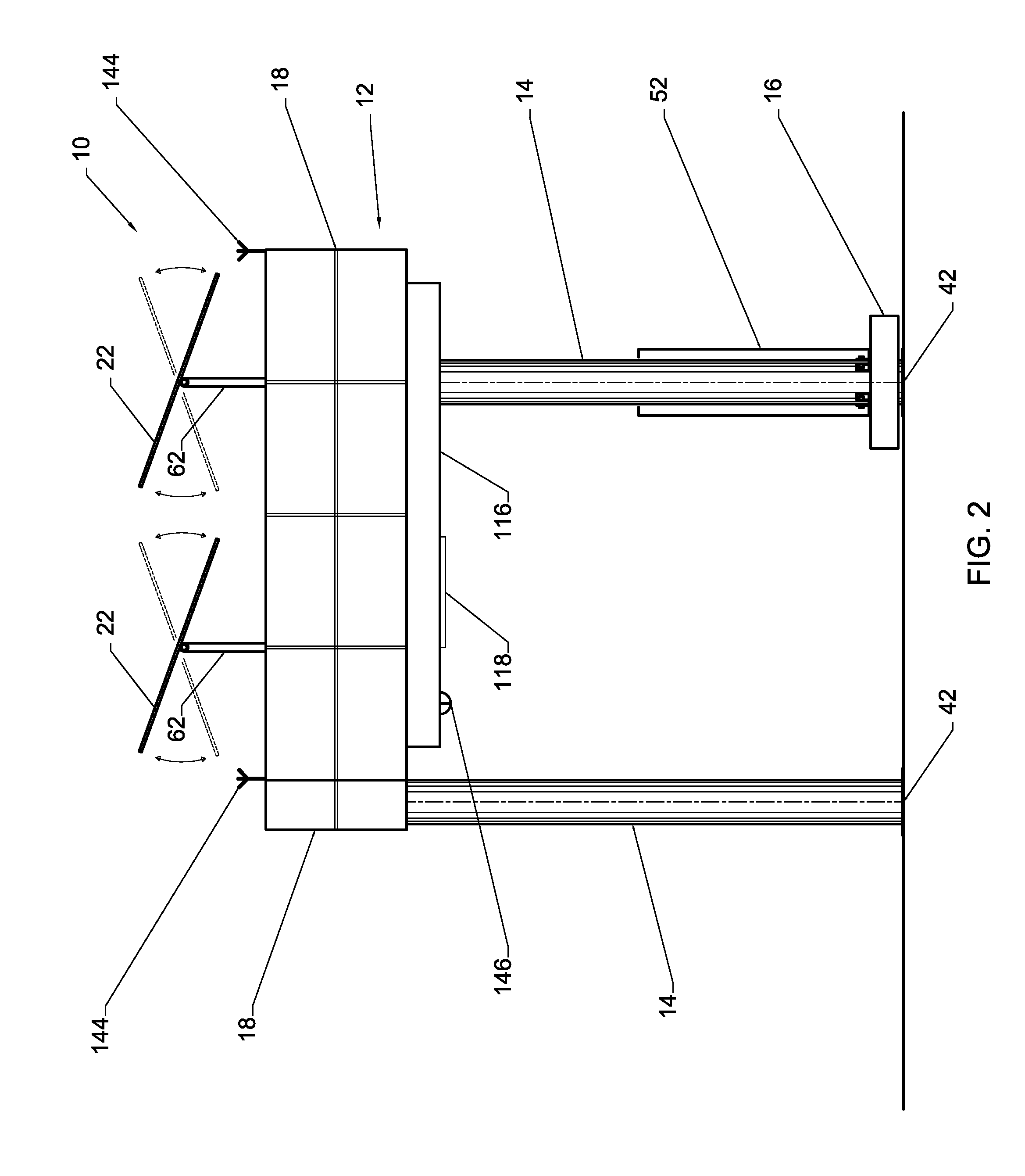
[0076]Referring generally to FIGS. 1-5, a modular, environmentally friendly mobile fuel distribution station 10 according to one embodiment of the present invention is shown. With specific reference to FIGS. 1 and 2, the environmentally friendly mobile fuel distribution station 10 includes a generally rectangular operation platform 12, a plurality of legs 14 that support the operation platform 12 in an elevated position above the ground and a central platform 16 that provides a service interface for patrons of the station 10. The operation platform 12 is covered by a plurality of modular panels 18 that function to both block from view, and protect, the main functional components of the station 10 housed within the operation platform 12, as discussed in detail below. As best shown in FIGS. 1 and 3, the central platform 16 is operatively connected to a pair of the legs 14. The legs 14, themselves, are joined together by rigid linkage elements 20, which provide increased rigidity and s...


PUM


Abstract

A modular, environmentally friendly mobile fuel distribution station includes a fuel tank, a support structure having a plurality of legs for supporting an operation platform in an elevated position a predetermined distance above ground, an alternative power generation device, the alternative power generation device being one of a solar power generator and a wind power generator for providing primary power to the mobile fuel distribution station and a central platform operatively connected to at least two of the legs, the at least two of the legs bearing the weight of the central platform, wherein the fuel tank and the alternative power generation device are disposed on the operation platform.

Description

FIELD OF THE INVENTION[0001]The present invention relates generally to fuel distribution stations and, more particularly, to a modular, environmentally friendly mobile fuel distribution station and related method of quickly transporting and assembling a mobile fuel distribution station.BACKGROUND OF THE INVENTION[0002]As more and more automobiles are put into service on roads across the globe to meet the transportation demands of an ever-expanding population, more and more fueling stations must be planned, permitted and constructed to provide a means of fuel distribution for such automobiles. The construction and operation of known fuel distribution and service stations, however, are lengthy, costly and resource-consuming undertakings. Surveys and studies of anticipated demand must be commissioned, the station designed in a configuration sufficient to meet the anticipated demand, permits must be pulled and a lengthy construction process commenced and completed before a single gallon...

Claims


Application Information

Patent Timeline
IPC IPC(8): B67D7/04
CPCB60S5/02E04H1/1233Y10T137/3802Y10T137/6855
Inventor CAJIGA, JOSE A.VILLAR, ARTURO CAJIGAVILLAR, VICENTE CAJIGA
Owner CAPAT LLC
Learn More