
Hydraulic system with a regulating circuit for controlling a motor vehicle transmission with automated actuation of clutches

Inactive Publication Date: 2012-05-15
SCHAEFFLER TECH AG & CO KG
View PDF5 Cites 0 Cited by
  • Summary
  • Abstract
  • Description
  • Claims
  • Application Information

AI Technical Summary

Benefits of technology

[0008]It is conceivable, in particular under cold conditions, that a back pressure occurs at valves of the hydraulic system, for example, intensified by one or more inlet screens, and that the back pressure results in an undesired reaction of the subsequent downstream servo system. In particular, it can cause the clutch pressure to be increased so high that a creep moment occurs at one of the two clutches of the motor vehicle transmission having automated actuation of clutches, although no clutch moment is requested. Advantageously, such a reaction triggered by the increased back pressure can be compensated for by means of the regulating circuit.
[0009]The object is also achieved with a hydraulic system for controlling a motor vehicle transmission having automated actuation of clutches, and with a first valve connected downstream from a hydraulic energy source for producing a system pressure. The first valve controls and / or regulates a clutch pressure, and a second valve is connected downstream from the first valve and ahead of two clutches of the motor vehicle transmission having automated actuation of clutches, to control and / or regulate the clutch pressure by connecting an orifice plate parallel to the clutches by means of a parallel branch. An additional flow-through can be produced through the first and second valves by the orifice plate, which valves are connected in series and ahead of the orifice plate, with a reaction from a possibly occurring back pressure advantageously playing a smaller role, i.e., with better regulation of the clutch pressure being possible.
[0011]Other preferred exemplary embodiments of the hydraulic system are distinguished by the fact that a control device of the regulating circuit contains the second valve. The regulating circuit can advantageously actuate the second valve, with direct influencing of the clutch pressure advantageously being possible. Advantageously, possible disturbance variables, caused for example by the back pressure, for example under cold conditions, can be compensated for.

Problems solved by technology

It is conceivable, in particular under cold conditions, that a back pressure occurs at valves of the hydraulic system, for example, intensified by one or more inlet screens, and that the back pressure results in an undesired reaction of the subsequent downstream servo system.
In particular, it can cause the clutch pressure to be increased so high that a creep moment occurs at one of the two clutches of the motor vehicle transmission having automated actuation of clutches, although no clutch moment is requested.

Method used


Image

  • Hydraulic system with a regulating circuit for controlling a motor vehicle transmission with automated actuation of clutches
  • Hydraulic system with a regulating circuit for controlling a motor vehicle transmission with automated actuation of clutches
  • Hydraulic system with a regulating circuit for controlling a motor vehicle transmission with automated actuation of clutches

Examples


Embodiment Construction

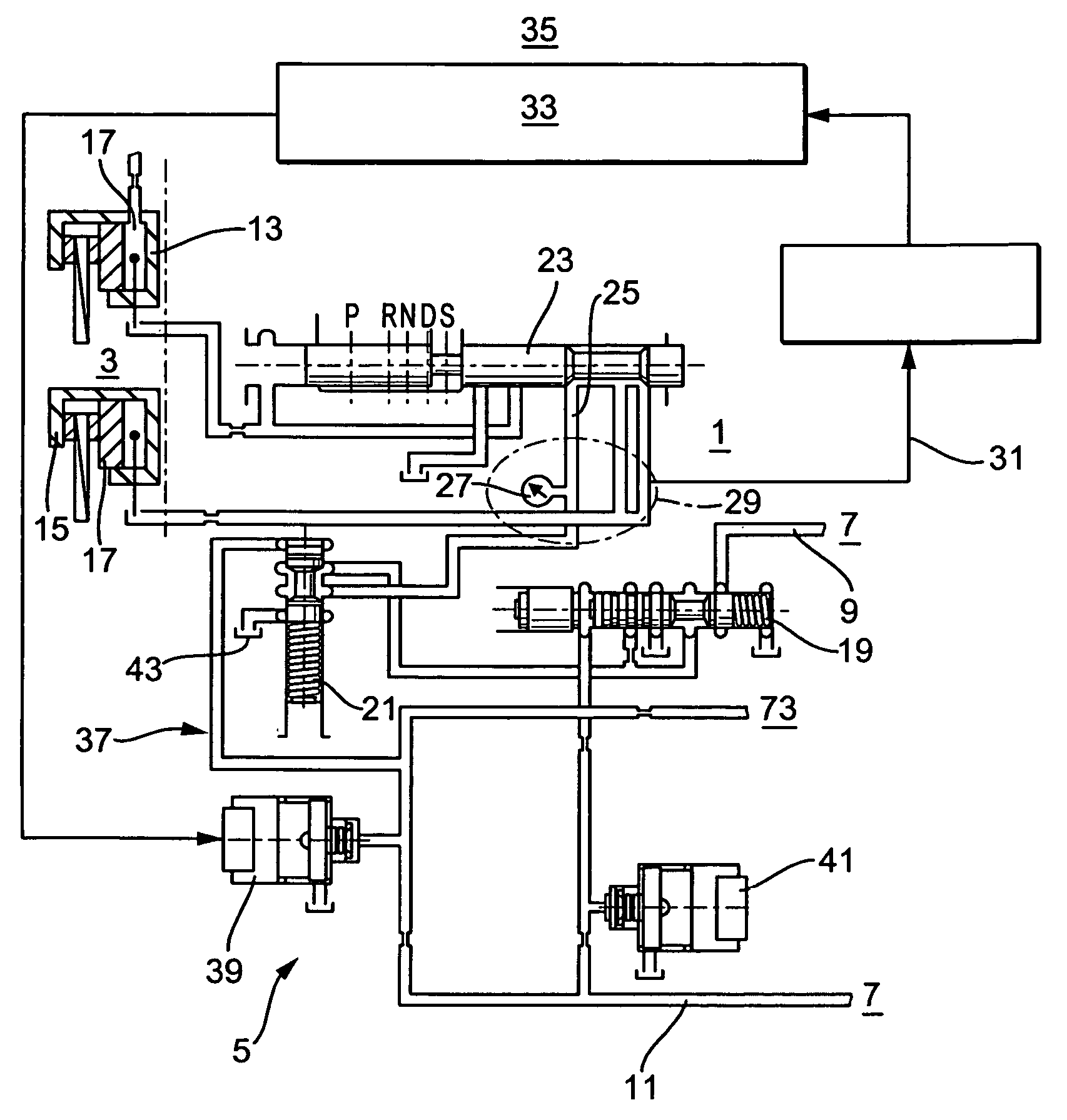
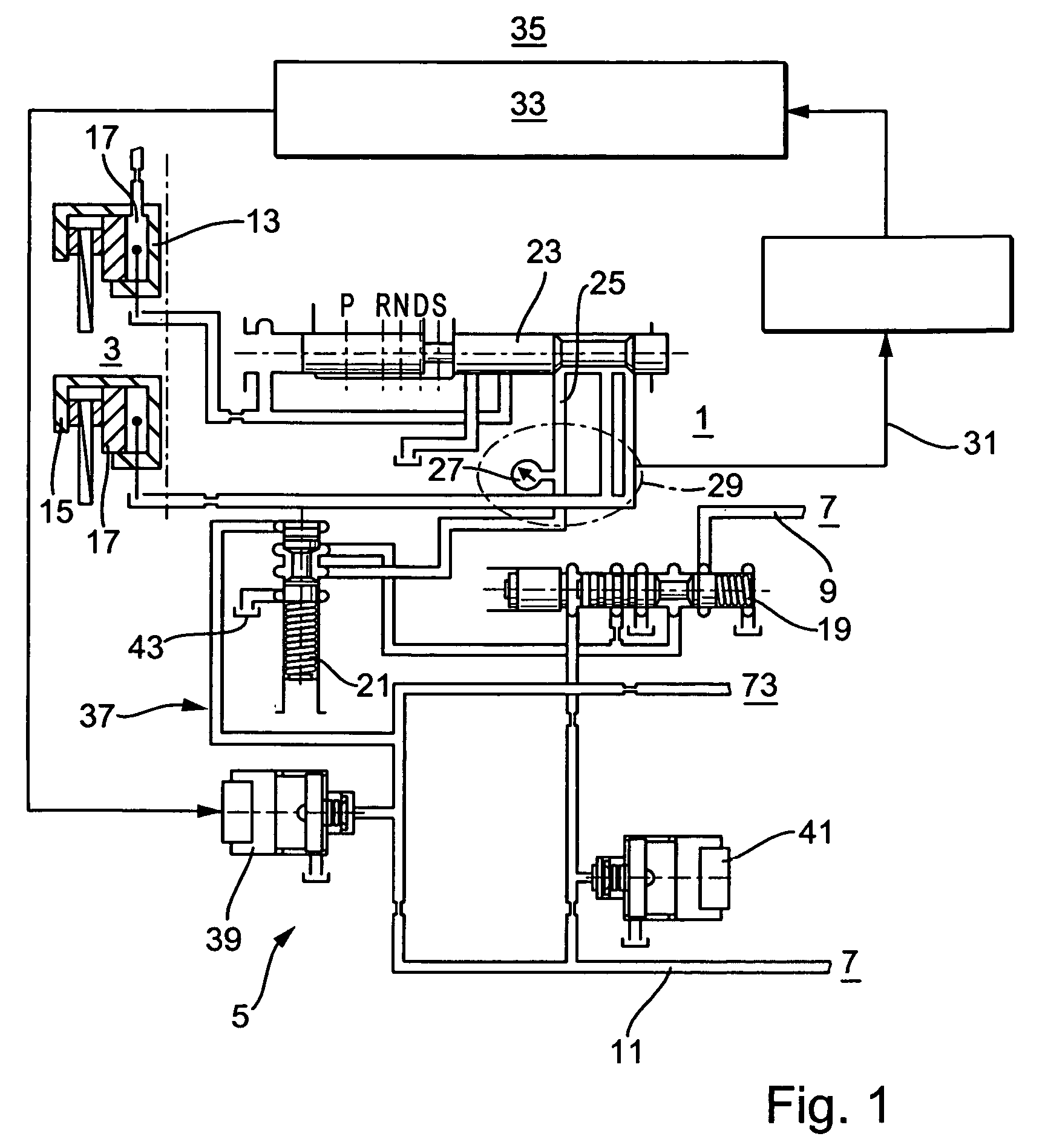
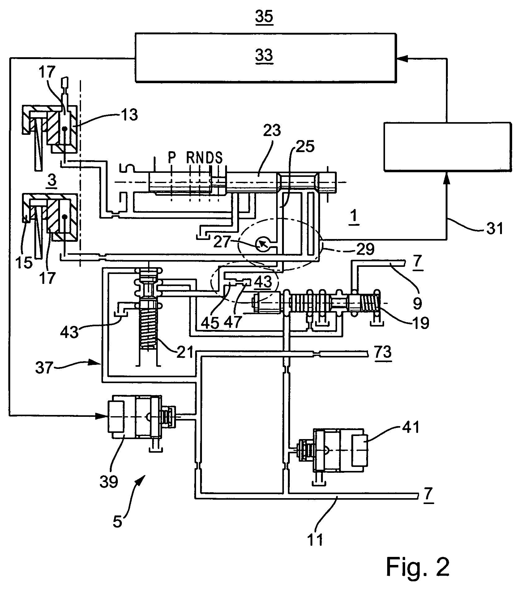
[0026]FIG. 1 shows a hydraulic system 1 for controlling a CVT 3 of a motor vehicle 5. The CVT 3 is part of a power train not shown in greater detail of motor vehicle 5, and can be assigned to a drive unit, for example a combustion engine and drive wheels. Hydraulic system 1 is suppliable with hydraulic energy by means of a hydraulic energy source that is merely indicated by means of reference label 7. Hydraulic energy source 7 can be a pump. Hydraulic energy source 7 is designed to provide a system pressure 9 and a preferably reduced pilot pressure 11. Additional hydraulic function elements, not depicted, for example valves, can be connected between hydraulic energy source 7 and the hydraulic system 1 shown in FIG. 1. CVT 3 has a first clutch 13 and a second clutch 15. First clutch 13 can be designed for example as a reverse travel clutch, and second clutch 15 as a forward travel clutch. Clutches 13 and 15 each have a pressurizable actuating cylinder 17, with clutches 13 and 15 bein...


PUM


Abstract

A hydraulic system for controlling a motor vehicle transmission having automated actuation of clutches. The hydraulic system includes a first valve connected downstream from a hydraulic energy source for producing a system pressure to control and / or regulate a clutch pressure. A second valve is connected downstream from the first valve and ahead of two clutches of the motor vehicle transmission to control and / or regulate the clutch pressure, wherein the second valve includes a regulating circuit to regulate the clutch pressure.

Description

BACKGROUND OF THE INVENTION[0001]1. Field of the Invention[0002]The present invention relates to a hydraulic system for controlling a motor vehicle transmission with automated actuation of clutches, the system including a first valve connected downstream from a hydraulic energy source for producing a system pressure, to control and / or regulate a clutch pressure. A second valve is connected downstream from the first valve and ahead of two clutches of the motor vehicle transmission with automated actuation of clutches to control and / or regulate the clutch pressure.[0003]2. Description of the Related Art[0004]Motor vehicle transmissions with automated actuation of clutches can be semi-automated, automated, or automatic transmissions. They are, for example, a shift transmission with electric clutch management, in which the clutch is actuated automatically, an automated shift transmission, for example a dual-clutch transmission, an automatic transmission with a stepped automation unit, o...

Claims


Application Information

Patent Timeline
IPC IPC(8): B60W10/02B60W10/10F16D25/10
CPCF16D48/0206F16D48/066F16H61/0206F16D2048/0221F16D2500/1027F16D2500/3024F16D2500/70406F16H59/72
Inventor MULLER, HOLGERSCHAUFLER, MARIO
Owner SCHAEFFLER TECH AG & CO KG
Learn More