
Diesel particulate filter and exhaust gas purification device

Active Publication Date: 2017-07-18
MITSUI MINING & SMELTING CO LTD
View PDF24 Cites 1 Cited by
  • Summary
  • Abstract
  • Description
  • Claims
  • Application Information

AI Technical Summary

Benefits of technology

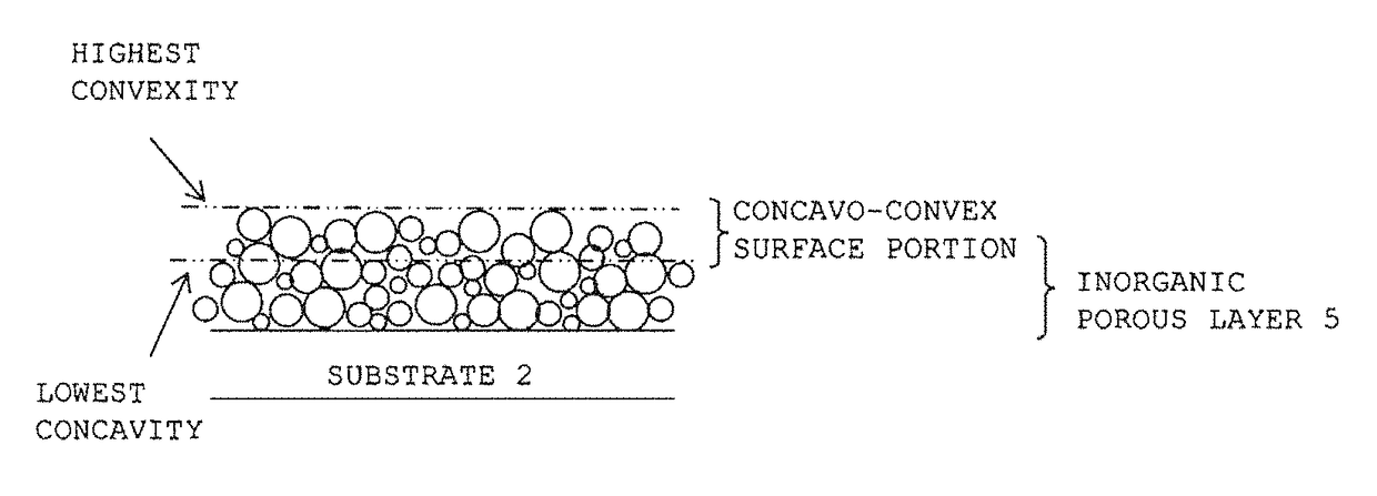
The invention is proposing a DPF with a surface that has gaps and bumps, which can collect PMs and improve combustion efficiency. The gaps and bumps also prevent back pressure and allow exhaust gases to flow through them. Adding a catalyst to the inorganic porous layer can further accelerate the combustion of PMs.

Problems solved by technology

A catalyst using a DPF had a problem that clogging of a filter was advanced with an increase of the amount of PMs to be collected, resulting in pressure loss.
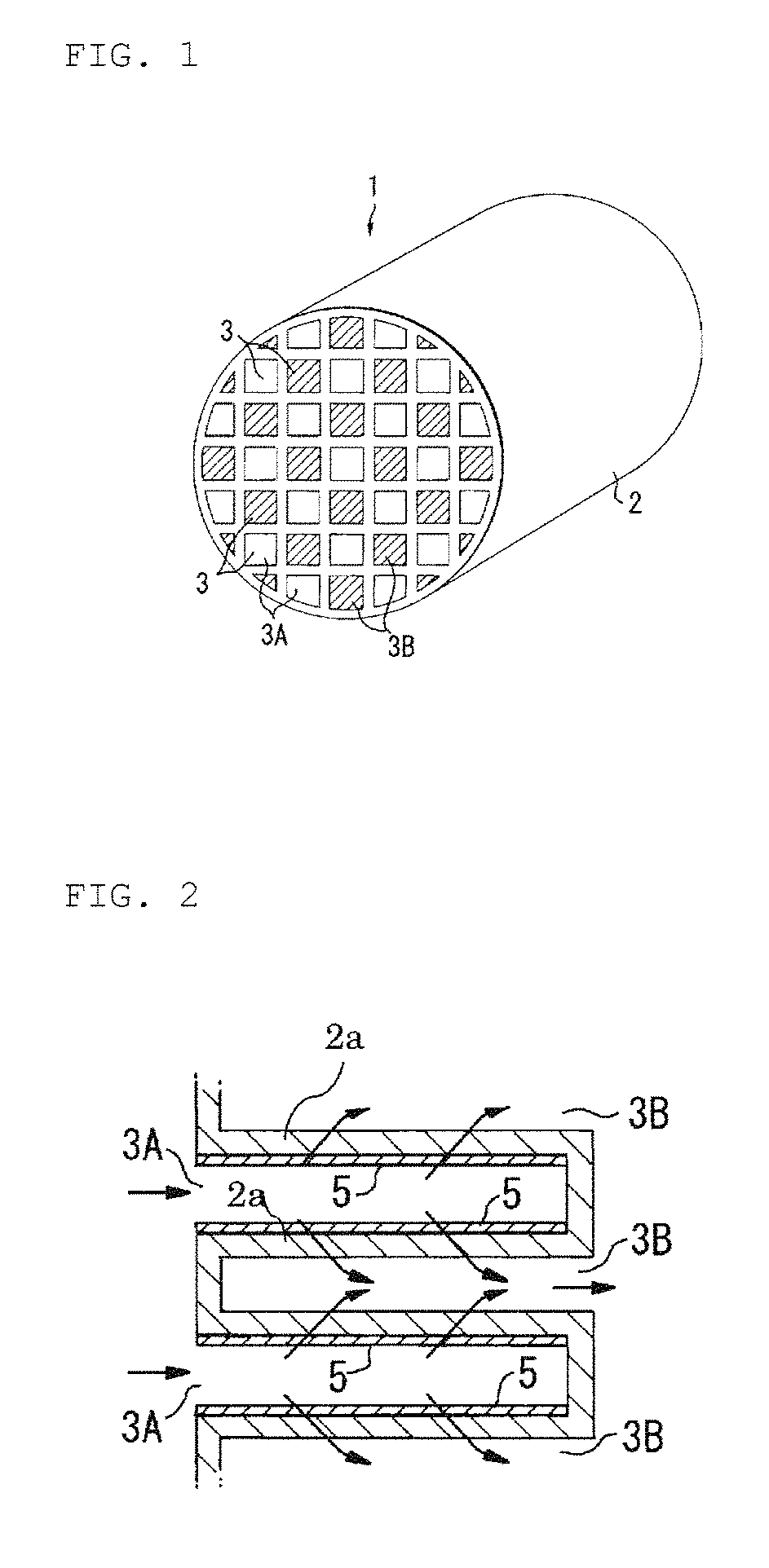
In the conventional DPF, however, the PMs are accumulated in an exhaust gas channel provided inside a dividing wall of a substrate, and as a result, there were problems that a flow of the exhaust gas become worse and thus a back pressure becomes higher.
In addition, as disclosed in Patent Document 5 described above, in the DPF in which the porous film having the pore size smaller than the size of pores of the dividing walls is provided on each surface of the dividing walls, the PMs are accumulated in the surface of the porous film, and as a result, there were problems that a flow of the exhaust gas become worse and thus a back pressure becomes higher

Method used


Image

  • Diesel particulate filter and exhaust gas purification device
  • Diesel particulate filter and exhaust gas purification device
  • Diesel particulate filter and exhaust gas purification device

Examples


example 1

[0121]A silver nitrate aqueous solution and a palladium nitrate aqueous solution were impregnated with Al2O3 (80 parts by mass) and were evaporated to dryness at 120° C. This material was calcined at 800° C. for 20 hours, and Ag and Pd were subjected to an alloying treatment to obtain AgPd alloy particulate firing catalyst powder. In this case, a mole ratio between Ag and Pd at the AgPd alloy was 5:1.

[0122]The AgPd alloy particulate combustion powder of 200 g, an alumina sol of 500 g having an alumina concentration of 20% by mass, and deionized water of 300 g were mixed with each other and the obtained mixture were subjected to a wet grinding treatment using a ball mill, thereby obtaining an AgPd slurry.

[0123]At this time, the ball mill was set to the following conditions: an alumina ball mill (size of 5 mm) was used; a number proportion of the ball mill with respect to the amount of the slurry was 30%; the number of rotations was 20 rpm; and a rotational time was 5 hours.

[0124]Para...

example 2

[0127]A particulate filter (sample) was obtained in the same manner as in Example 1 except that the conditions of the ball mill in Example 1 were changed into the following conditions: an alumina ball mill (size of 5 mm) was used; a number proportion of the ball mill with respect to the amount of the slurry was 30%; the number of rotations was 30 rpm; and a rotational time was 5 hours. In this case, a thickness of the inorganic porous layer was 30 μm.

example 3

[0128]A particulate filter (sample) was obtained in the same manner as in Example 1 except that the conditions of the ball mill in Example 1 were changed into the following conditions: an alumina ball mill (size of 10 mm) was used; a number proportion of the ball mill with respect to the amount of the slurry was 30%; the number of rotations was 20 rpm; and a rotational time was 5 hours. In this case, a thickness of the inorganic porous layer was 30 μm.


PUM

PropertyMeasurementUnit
Fractionaaaaaaaaaa
Fractionaaaaaaaaaa
Thicknessaaaaaaaaaa

Abstract

Provided is a novel DPF which can prevent PM from accumulating on the surface and interior of a filter substrate, and can suppress an increase in back pressure caused by exhaust gas. The DPF has a configuration in which an inorganic porous layer, which includes a metal oxide or a metal composite oxide and provided with surface irregularities having a thickness of at least 50% of the thickness of the inorganic porous layer, is formed on part or all of the surface of the dividing wall on the side where exhaust gas flows in.

Description

TECHNICAL FIELD[0001]The present invention relates to a diesel particulate filter (referred to as a “DPF”) used for purifying an exhaust gas discharged from an internal combustion engine, more particularly, diesel engine, and an exhaust gas purification device using the same.BACKGROUND ART[0002]Exhaust gases discharged from a diesel engine contain sulfate based on a sulfur content in fuel, tar-like particulate matter (referred to as “PM”) resulting from incomplete combustion, nitrogen oxides (NOx), and the like.[0003]As a device for removing the PM contained in the exhaust gas of the diesel engine, an exhaust gas purification device for collecting the PM using a DPF and burning away the collected PM with proper timing is known.[0004]Such a DPF is typically designed such that a porous filter substrate exhibiting a honeycomb structure makes up framework, and when the exhaust gas circulates inside a dividing wall of the substrate, the PM is collected in the surface of the dividing wall...

Claims


Application Information

Patent Timeline
IPC IPC(8): F01N3/035B01D53/94B01D46/24B01J37/02F01N3/022B01J35/04B01J23/50B01J23/42B01J23/44B01J23/46
CPCF01N3/035B01D46/2418B01D53/94B01D53/944B01J23/50B01J35/04B01J37/0248F01N3/0222B01D2255/104B01D2255/1021B01D2255/1023B01D2255/1025B01D2255/9155B01D2258/012B01J23/42B01J23/44B01J23/464B01J35/56
Inventor DAIDO, ATARUKOGAWA, TAKAHIRO
Owner MITSUI MINING & SMELTING CO LTD
Learn More